| These Pages include various standards. To confirm the status of any standard, identify the replacement standard if it is obsolete and/or purchase the standard please use. It is also possible to become a BSI member and obtain copies of the Standards at much reduced prices. |
Reinforced concrete beams subject to bending moments
The building structures pages have been added over the six months to Dec. 2012. They are very much work-in-progress and I will be updating them on a regular basis over the next six months.
|
Introduction
This page includes note covering the theory of reinforced concrete beams. The theory generally used in the past has bee based on elastic method of analysis. In the last twenty years the elastic theory has beean superseded by the ultimate load method in the codes applicable to the construction industry. The notes below consider , in outline, both methods. symbols
Elastic theory The basis of this theory is provided on webpage Composite beams
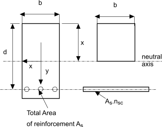
The modular ratio nsc = Es /Ec. Multiplying the area of the reinforcement bars by the modular ratio results in the area reinforcement being effectively transformed into an equivalent area of concrete....Taking moments of areas about the neutral axis results in the equation
This when rearranged results in the quadratic
The only relevant solution to this equation is the positive value
The second moment of area Ic of the transformed section is
The maximum stress in the concrete at the extreme fibre is
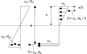
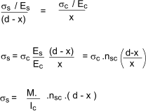
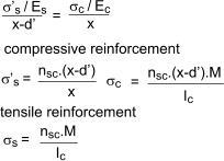
The strain diagram shown above may be used to calculate the stress in the reinforcement. The strain diagram is linear throughout the depth since the beam section is assumed to remain plane during bending. Therfore
Moment of Resistance of beam This is the moment withstood by the beam when the stress in the concrete or the steel reaches the maximum allowable value. The value for the concrete and steel is calculated easily from the stress diagram
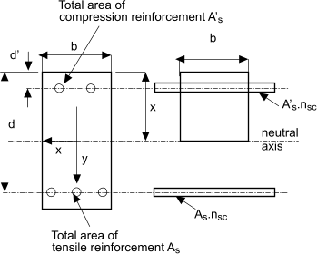
The moment of resistance of the beam according to elastic theory is the lesser of Mrc or Mrs Reinforcement in compression zone of beam For a beam of given cross section dimensions there is a point when increasing the area of the reinforcement does not provide a resulting increase in the moment of resistance because the concrete becomes the limiting factor. This limitation can be overcome by adding reinforcement in the compression zone of the beam. Consider a beam as shown below
Taking moments of area about the neutral axis
The second moment of area of the transformed section is therefore
The maximum stress in the concrete at the extreme fibre is
Ultimate load theory Ultimate load theory for concrete beams is based on the calculated moment of resistance (ultimate moment of reistance) being based on
the failure strength of concrete in compression and the yield strength of the reinforcement of the steel in tension both modified by
a margin of safety. However concrete generally fails suddenly while the failure of steel is generally
progressive . The margins are typically 1,5 for concrete and 1,15 for steel. When the characteristic
stength for concrete is based on the cube strength it is necessry that it is multiplied by 2/3 because the stength in bending
is always significantly less than that resulting from the cube strength.
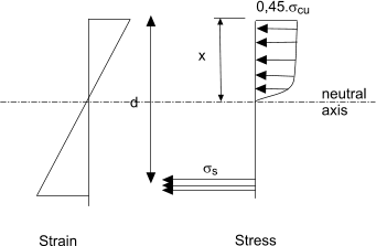
The ultimate load theory analysis is based on the assumptions that plane surfaces remain plane during bending and there is no contribution to the bending strength of the beam from concrete in tension. The strain therefore varies uniformly down the beam section. The stress diagram however is not linear but has a rectangular parabolic shape as shown below.
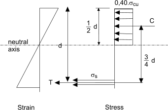
A reasonably accurate approximation of this curve which is used in strength calculations is shown below
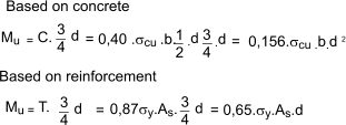
The moment of resistance in this instance is identified as the ultimate moment of resitance Mu and is easily calculated as shown below
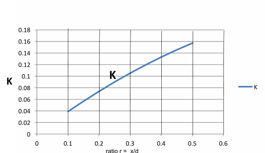
The section considered above identifies the ultimate moment of resistance when the neutral axis
is 0,5.d . A lower design moment would have a requirement for a section with a reduced value of x to the
neutral axis. It is easily possible by evaluating moment of resistance of a section resulting from different
values of the ratio of x/d by taking moments about the tensile reinforcement.
A plot of K vs r= x/d is easily plottted
|
Useful relevant Links
|
|
