Introduction.... Superposition.... Nomenclature.... Simple Bending.... Deflection.... Area Moment Method.... Composite Beams....
|
Introduction The stress, strain, dimension, curvature, elasticity, are all related, under certain assumption,
by the theory of simple bending. This theory relates to beam flexure resulting from
couples applied to the beam without consideration of the shearing forces. Superposition Principle The superposition principle is one of the most important tools for solving beam
loading problems allowing simplification of very complicated design problems.. Nomenclature
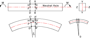
e = strain Simple Bending A straight bar of homogeneous material is subject to only a moment at one end and an equal and opposite moment at the other end...
The beam is symmetrical about Y-Y H'G'/E'F' =(R+y)θ /R θ = (R+y)/R And the strain e at layer H'G' = e = (H'G'- HG) / HG = (H'G'- HG) / EF = [(R+y)θ - R θ] /R θ = y /R The accepted relationship between stress and strain is σ= E.e Therefore σ = E.e = E. y /R
Therefore, for the illustrated example, the tensile stress is directly related to the distance above the neutral axis.
The compressive stress is also directly related to the distance below the neutral axis. Assuming E is the same for
compression and tension the relationship is the same.
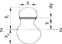
This can only be correct if Σ(yδa) or Σ(y.z.δy) is the moment of area of
the section about the neutral axis. This can only be zero if the axis
passes through the centre of gravity (centroid) of the section.
From the above the following important simple beam bending relationship results
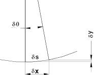
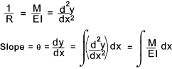
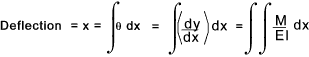
It is clear from above that a simple beam subject to bending generates a maximum stress at the surface furthest away from the neutral axis. For sections symmetrical about Z-Z the maximum compressive and tensile stress is equal. σmax = ymax. M / I The factor I /ymax is given the name section Modulus (Z) and therefore σmax = M / Z Values of Z are provided in the tables showing the properties of standard steel sections Deflection of Beams Below is shown the arc of the neutral axis of a beam subject to bending.
For small angle dy/dx = tan θ = θ
From this simple approximation the following relationships are derived.
Integrating between selected limits.
It has been proved ref Shear - Bending
that dM/dx = S and dS/dx = -w = d2M /dx
If w is constant or a integratatable function of x then this relationship can be used to
arrive at general expressions for S, M, dy/dx, or y by progressive integrations with a constant
of integration being added at each stage. The properties of the supports or fixings
may be used to determine the constants. (x= 0 - simply supported, dx/dy = 0 fixed end etc )
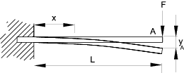
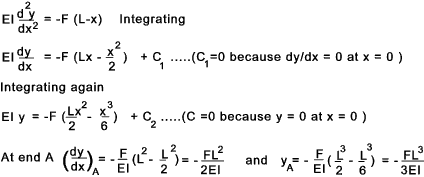
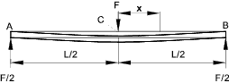
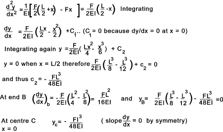
Singularity functions can be used for determining the values when the loading a not simple ref Singularity Functions Example - Cantilever beam Consider a cantilever beam (uniform section) with a single concentrated load at the end. At the fixed end x = 0, dy = 0 , dy/dx = 0 From the equilibrium balance ..At the support there is a resisting moment -FL and a vertical upward force F. Consider a simply supported uniform section beam with a single load F at the centre. The beam will be deflect symmetrically about the centre line with 0 slope (dy/dx) at the centre line. It is convenient to select the origin at the centre line.
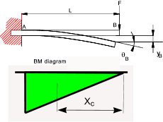
Moment Area Method This is a method of determining the change in slope or the deflection between two points on
a beam. It is expressed as two theorems... Example 1) Determine the deflection and slope of a cantilever as shown..
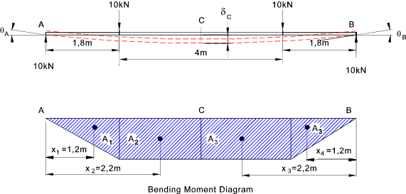
The bending moment at A = MA = -FL Example 2) Determine the central deflection and end slopes of the simply supported beam as shown.. E = 210 GPa ......I = 834 cm4...... EI = 1,7514. 10 6Nm 2
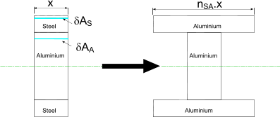
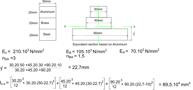
A1 = 10 . 1,8 . 1,8 /2 = 16,2kNm2 The slope at A is given by the area of the moment diagram between A and C divided by EI. θA = (A1 + A2) /EI = (16,2+36).10 3 / (1,7514. 10 6) The deflection at the centre (C) is equal to the deviation of the point A above a line that is tangent to C. δC = (AM.xM) /EI = (A1 x1 +A2 x2) / EI = 120,24.10 3/ (1,7514. 10 6) Composite Beams Beams constructed of more than one material can be treated by using the equivalent width technique if the maximum stresses in each of the materials is within the relevant materials elastic limit. Consider a composite beam as shown below. The steel has an elastic modulus ES = 210.103 N/mm2 and the aluminium has an EA = 78.103 N/mm2.
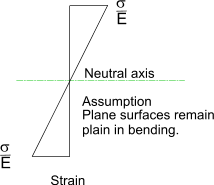
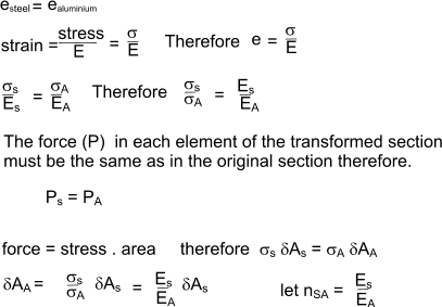
The composite beam is analysed on the basic assumption that plane surfaces remain plane during bending within the elastic limit therefore down the full depth of the beam the strain (deflection /original length) is constant i.e the deflection is proportional to the distance from the neutral axis of the beam. The strain is equal to the (stress /Youngs Modulus(E)) Refer to figure below
Now to obtain the equivalent section which is all aluminium the dimensions of the replacement aluminium must be such that the mechanical properties are equivalent to the original material. The overall depth of the transformed section is the same as the orginal section. The resulting strain in any element dA of the transformed section must constant.
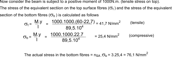
The equivalent area of the transformed section based on aluminium is equal to the area of the original steel section x nSA. If the depth of the transformed section is the same as the original section then the width of the transformed aluminium section is equal to nSA x width of original steel section. The equivalent area of the aluminium section must be subject to the same strain as original steel section positioned at the same distance from the section neutral axis. The simple beam theory can be used to calculate the bending stresses in the transformed section. The actual stresses will, of course, be n x the calculated stresses in the transformed section. Example on composite beams Consider a composite beam comprising steel, brass, and aluminium sections. Produce an equivalent section based on Aluminium. Calculate the position of the neutral axis and the moment of inertia of the equivalent section.
|
Sites Providing Relevant Information
|
|