Introduction
This page includes some notes on bricks and blocks as used in the construction of walls
and structures..
Masonry construction is typified by the use of units which can be positioned by hand. The units, brick or blocks
a fixed using mortar. Masonry is generally strong in compression but has limited flexural strength. Structures from bricks and or
blocks should be designed to limit any tensile or buckling loads especially in slender members . Excessive crushing forces should also b
e avoided. An important limitation resulting from masonry construction is the inherent weakness for withstanding high seismic loads.
When specifying masonry construction in earthquake regions additional requirements are necessary as outlined in BS EN 1998 Eurocode 8: Design of structures for earthquake resistance.(seismic design)
This page includes various general notes on masonry construction.
More detailed design notes for masonry construction are provided on webpage Masonry design
Relevant Standards
BS EN 1996-1-2 : 2005 .. Eurocode 6. Design of masonry structures. General rules. Structural fire design
and structures..
BS EN 1996-2 : 2006... Eurocode 6. Design of masonry structures. Design considerations, selection of materials and execution of masonry
BS EN 1996-3 : 2006... Eurocode 6. Design of masonry structures. Simplified calculation methods for unreinforced masonry structures
Construction Units
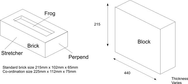
Brick Types
Clay Bricks
Clay bricks are made from suitable clay earths found around the UK , the brickworks generally located
adjacent to the raw materials site. Bricks are moulded by machine and then subject to continuous
firing in a kiln . The bricks are generally located on metal trolleys and moved through kilns where
the heat is set in stages to drive of the moisture , fuse the bricks and then anneal them.
Engineering bricks
Engineering bricks are clay bricks made from constituents allowing the resulting bricks to be far
stronger than the usual ones. These bricks are used for high stress conditions where great durability and
water resistance is required. These bricks are mainly sourced at Southwater(Red) and Staffordshire(blues).
Calcium Silicate
Sand lime and flint lime bricks are not fired . They are moulded as a cementacious mixture and allowed to harden
much as concrete . The mix is normally very dry and under considerable pressure. The resulting
bricks are very smooth and accurate. The bricks are supplied in blues , pinks and yellows. The colours
resulting from pigment incorporated in the mix by different manufacturers.
Concrete bricks.
Concrete bricks are sharp and smooth. Because they are hardened naturally they suffer
from shrinkage during the setting and afterwards.
Table of brick properties
| Material | Class | Water Absorption | Typical unit compressive strength (N/mm2) |
Fire clay bricks
BS 3921 |
Engineering A
Engineering B
Facing bricks
Commons (class (1-15)
Class 1
Class 2
Class 3
Class 15
Flettons
Stocks(bricks without frogs) |
< 4.5%
= 7%
= 10-30%
= 20-24%
= 15-25%
= 20-40% |
> 70
>50
=10-50
=7
=14
=20
=105
=15-25
=3-20 |
Calcium silicate
BS 187 |
Class 2 -7 |
- |
= 14 - 48,5 |
Concrete Blocks
BS 6073-Pt1 |
- |
- |
= 7- 20 |
Concrete Blocks
BS 6073-Pt1 |
Dense Solid
Dense hollow
Lightweight |
- |
= 7, 130
= 3,5 7 10
= 2,8 3,5 4,7 |
Reconstituted stone
BS 6457 |
Dense Solid |
- |
As dense concrete blocks |
Brick Bonding
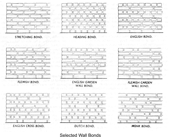
The bonding of bricks is important to its performance as a structural material. Various bonds
exist, some more attractive than others. while some special bonds related to reinforced brick work. Cavity walls employ stretching
bonds where each skin of the wall is laid a half brick thick and the only headers shown are at reveals and quoins (corners). Other
bonds show both headers and stretcher faces.
Selected wall bond patterns
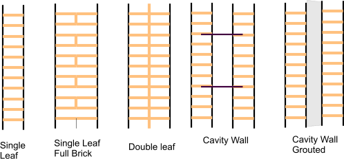
Types of Masonry Walls
| Single-leaf wall- defined as a wall without continuous vertical joint or cavity |
| Double-leaf wall- defined as a wall constituted from two parallel leaves and a joint between them max 25 mm, filled with mortar. The leaves can be tied together with steel wall ties to achieve solid wall cross section
| | Cavity wall- defined as a wall constructed of two parallel single-leaf walls, tied together with wall ties or bed joint reinforcement. One or both leaves can be load-bearing. The cavity between the leaves can be filled, or partially-filled, with non-load bearing insulation material |
| Grouted cavity wall- defined as a wall like the cavity wall but the two leaves are spaced min 50 mm apart and are tied securely in place with steel wall ties and bed joint reinforcement, and with a cavity filled with concrete. |
Mortars
The mortar is used to bond the bricks together in construction of walls etc. The mortar should
have similar properties to the relevant bricks. It should specially have the same thermal
expansion properties to avoid developing cracks over time. It is better if the mortar is
slightly weaker than the bricks it is bonding.
Two main mixes of mortar are used 1) Gauged mortar composed of portland cement, hydrated lime and sand.
2) Cement mortar composed of portland cement and sand, The latter is hard and relatively
intolerant to movement but strong and durable. Gauged cement is not as strong and durable but
is more flexible with limited plasticity.
The water cement ratio is quite critical in the production of the mortar.
The higher the ratio of water the immediate weaker the resulting mortar but the better is the workability.
Mortem Mixes
| Mortar Class | Comp.Strength Class | Cement : Lime : Sand |
Cement : Sand | Compressive Strength after 28 days (N/mm2) |
| Dry Pack |
- | 1 : 0 : 3 | - |
|
| I | M12 | 1 : 0-1/4 : 3 |
| 12 |
| II | M6 | 1 : 1/2 : 4-41/2 | 1 : 2,5-3,5 | 6 |
| III | M4 | 1 : 1 : 5-6 | 1 : 4-5 | 4 |
| IV | M2 | 1 : 2 : 8-9 | 1 : 5,5-6,5 | 2 |
Cavity walls is house construction
Cavity walls didn't really start to be used in general UK building construction until the early 1930s.
From 1932 to 1982 cavity wall construction became more and more popular. After 1982 nearly all domestic houses were build with cavity walls.
A cavity wall is around 300mm wide (two 4.5 inch bricks and a 2.5 inch cavity) while a solid wall is around 230mm wide (a 9 inch header brick without a cavity).
Cavity walls have outer visible bricks generally with a stretcher bond construction. Non cavity walls generally have a Flemish bond English bond
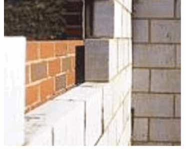
outer layer. In most recent times the outer leaves have been constructed from bricks and the inner walls from light density concrete blocks.
The two leaves tied together using metal ties inserted into the mortar spaces during construction
Masonry Arches
In the early days of construction one of the fundamental problems in construction is the bridging of openings e.g.rivers.
The simplest solution is a horizontal beam supported by walls or columns . There were two primary building materials: timber and stone.
The latter had many advantages but had the major disadvantage that stones and bricks are brittle and can not withstand tensile stresses.
To overcome this problem masonry arches were developed . These allow spans to be construct with the primary building elements
only withstanding compressive stresses.
Arches were used in Egypt and Iraq centuries before the birth of Christ and were used extensively by the Romans for the construction of bridges, and for the aqueducts built from about 300 B.C.
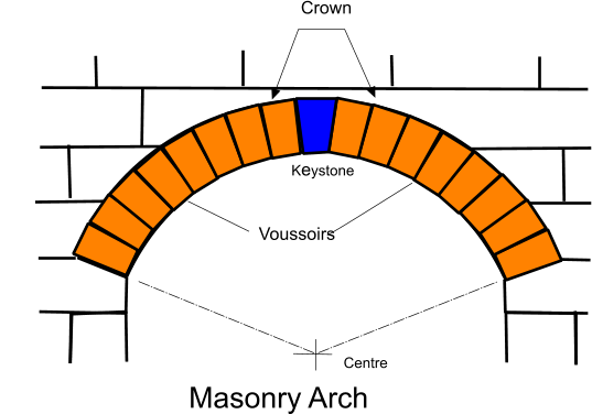
Masonry arches made from shaped stones have been constructed with spans exceeding 100m
Properties of Masonry as built
| Property | Units | Masonry Type |
| Clay brick work | Calcium Silicate brick work | Dense concrete block work |
Aerated concrete blocks | Natural limestone |
| Specific Gravity | | 2,2 | 2,0 | 2,1 | 0,9 | 2,2 |
| Density | kN/m3 | 22 | 20 | 21 | 9 | 22 |
| Elastic Modulus | kN/mm2 | 5-25 | 14-18 | 5,0-25 | 2-8 | 15 |
| Creep Factors - final creep strain to elastic strain at working stress | | 1,2-4,0 | - | 2,0-7,0 | 2,0 | - |
| Reversible moisture movement % | % | 0,02 | 0,01-0,05 | 0,02-0,04 | 0,02-0,03 | 0,01 |
| Initial moisture expansion (+) or drying shrinkage (-) % | % | +0,02-+0,08 | -0,01--0,05 | -0,02--0,06 | -0,05--0,09 | +0,01 |
| Coefficient of thermal expansion x 106 ** | (oC))-1 | 5-8 | 8-14 | 6-12 | 8 | 4 |
| Thermal conductivity at 5% moisture content | W/m oC | 1,3 | 1,2 | 1,2 | 0,3 | 1,3 |
** example for clay brick work 5.10-6 - 8.10-6
Lintels
A lintel is a horizontal beam over a door or window opening usually carrying the load of the wall above.
Lintels can often be partially or completely hidden from view.
There are many different shapes of lintels, determined by the properties of the material and the purpose for which the lintel is required.
Concrete lintels are generally rectangular, although variations of the rectangular configuration are available for use in cavity walls.
The development of concrete and steel lintels for larger span opening in the 1950's and 1960�s, were required to carry the increased loads.
Windows up to 2.4m wide are not uncommon and these larger spans require more attention to be paid to the bearings at the ends of these lintels resulting from the
increased loads from them onto the masonry below. Lintels specifically designed for cavity wall construction are also available
Concrete lintels are generally provided precast or preformed from manufacturers and links are provided to typical manufacturers literature for detail design review
reference standard
BS 5977-1:1981 Lintels. Method for assessment of load
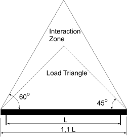
The method of assessing loads on lintels in masonry structures for openings up to 4,5m in single storey structures
and up to 3,6m in normal 2 and 3 storey domestic structures is described in BS 5977. Typically there should not be less than 0,6m
opr 0,2L of masonry to each side of the opening (L is the clear span). and not less than 0,6m masonry above the lintel at mid span and not less then
0,6m of masonry over the lintel supports.
The loading on the lintel is based on the following assumptions
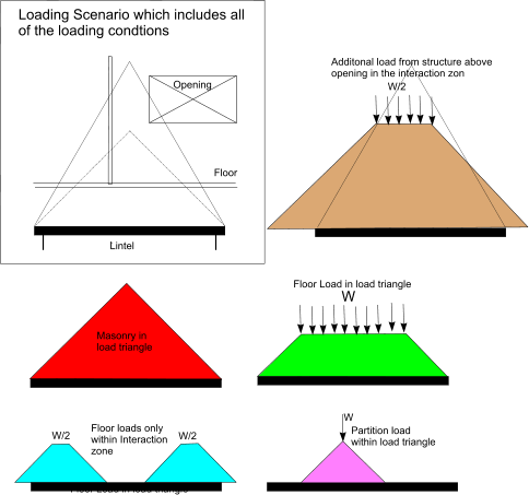
1) The weight of the masonry in the loaded triangle as shown above is carried by the lintel.
2) Any point load or distributed load applied within the load triangle is dispersed at 45o and carried by the linter
3) Half of any point or distributed load applied to the masonry within the zone of interaction is carried by the lintel
Loads above the lintel which are outsize the zone of interaction need not be considered.
Concrete lintels
Concrete lintels can be basic precast reinforced or prestressed. The latter having the highest load bearing capacity.
Concrete lintels can be composite or non composite
Composite lintels utilise the composite action of the concrete and brick/block work together to provide the load-bearing capacity. This option
generally requires A strong mortar mix and brick reinforcing fully interleaving each course.
Non-composite concrete lintels are based on the load bearing capacity of the lintel itself with it internal reinforcement. This option provides higher load bearing
capacity and does not require propping during construction.
Simple sketch showing conditions for a concrete lintel

Table showing a typical non- composite precast reinforced concrete beam (150mm x 100mm) load bearing capacity.
Section (w x h)
mm |
Maximum UDL kg/m for Clear Span (m) |
| 0,75 | 0,9 | 1,05 | 1,2 | 1,35 | 1,5 | 1,65 | 1,8 | 1,96 | 2,1 | 2,25 | 2,4 | 2,55 | 2,7 | 2,85 | 3,0 | 3,15 | 3,3 |
| 150 x 100 | 2381 | 1739 | 1282 | 1006 | 808 | 662 | 551 | 464 | 395 | 340 | 295 | 257 | 226 | 199 | 176 | 157 | 140 | 125 |
Profiled steel lintels
Profiled galvanised steel or stainless steel are very useful for cavity wall construction because they can be formed to
support both leaves and also incorporate insulation in the section. Detailed information on steel lintels is found in the links
at the foot of this page. There are numerous steel lintel profiles for solid and cavity walls..A typical cavity wall lintel with
provision for insulation is shown below
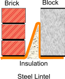
Table showing a set of load bearing properties for a typical standard lintel of the above shape suitable for
a 95mm external leaf, 85mm gap and a 100mm internal leaf and a lintel height of 100mm). The relevant section has properties
Ixx 374.64 cm4
Zxx 37.76 cm3
Weight 13.46 kg/m
Area 17.14 cm2
| Opening Span (mm) |
Lintel Length(mm) |
Safe Load (kN) |
| 600 | 900 | 30 |
| 750 | 1050 | 30 |
| 900 | 1200 | 30 |
| 1050 | 1350 | 30 |
| 1200 | 1500 | 30 |
| 1350 | 1650 | 30 |
| 1500 | 1800 | 28 |
| 1650 | 1950 | 25 |
| 1800 | 2100 | 23 |
| 1950 | 2250 | 22 |
| 2100 | 2400 | 20 |
| 2250 | 2550 | 19 |
| 2400 | 2700 | 18 |
| 2550 | 2850 | 17 |
| 2700 | 3000 | 16 |
For this table the safe load in the total load which is uniformly distributed over the length of the opening span.
The manufacturers technical literature includes a very diverse range of lintel sections with a wide range of
properties. See links below
|


