These Pages include various standards. To confirm the status of any standard, identify the replacement standard if it is obsolete and/or purchase the standard please use. It is also possible to become a BSI member and obtain copies of the Standards at much reduced prices.


Structures Index
Timber Design to Eurocodes
Timber Connections

Note:

This page includes notes related to the relevant Eurocodes EC5 ( BS EN 1995-1-1 ). On the Roymech website I have also provided information on timber which relates to BS 5268 Timber Index this is now superseded by the eurocode.    My information on the older standards is generally more detailed and much of the information is still relevant.

Introduction.... Formwork.... Standards.... Symbols.... Loading on lateral joints .... Characteristic Embedment strengths.... Edge and distance spacing..... Screws.... Nails.... Bolts... Dowels....

The building structures pages have been added over the six months to Dec. 2012.     They are very much work-in-progress and I will be updating them on a regular basis over the next six months.

Introduction

This page includes notes on design of timber connections including nails, screws, dowels and bolts.    The notes are outline in nature suitable for enabling basic calculations.  For detailed design it is necessary to refer to the actual standard and all of the associated standards.

In timber constructions the various timber members are generally connected using nails, screws, dowels, bolts, metal plates, adhesives and basic wood joints.     Carpentry joints have been used for connecting timber members throughout history       (ref Timber Joints ) but these are now primarily used for furniture work and aristic construction projects.    Carpentry joints are not mentioned in Eurocode 5.    Connections made with adhesively bonded joints are also not discussed in the Eurocode .


Relevant Standards

.

Code Reference Number                Title
BS EN 1990 Eurocode 0: Basis of structural design
BS EN 1995-1-1:2004 Eurocode 5. Design of timber structures. General. Common rules and rules for buildings
BS EN 1995-1-2:2004 Eurocode 5. Design of timber structures. General. Structural fire design


symbols
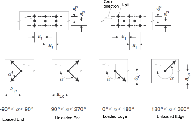
a1 = fastener spacing parallel to grain
a2 = fastener spacing perpendicular to grain
a3,t = fastener end spacing parallel to grain. Loaded end
a3,c = fastener end spacing parallel to grain. Unloaded end
a4,t = fastener edge spacing parallel to grain. Loaded end
a4,c = fastener edge spacing parallel to grain. Unloaded end
d = fastener diameter
def = effective fastener diameter
F v,Rk =Characteristic load-carrying capacity per shear plane per fastener
kxxx = Factor used in calulations

n = the number of fasteners in line parallel to grain
nef = the effective number of fasteners in line parallel to grain
t i = timber or board thickness or penetration depth with i = 1 or 2
fc,90,k = characeristic compressive strength of timber perpendicular to grain.
f h,i,k =Characteristic embedment strength in timber member i
d = fastener diameter
Emean = Mean value of Modulus of Elasticeity
Gmean = Mean value of shear Modulus
M y,Rk =Characteristic fastener yield moment
β = Ratio between embedment strength of the members
α =Angle typically between force and grain direction/ load and loaded edge etc
ρ =density
F ax,Rk = Characteristic axial withdrawel capacity of fastener
F ax,Rd = Design axial withdrawel capacity of fastener


Load Carrying capacity of nails , bolt, screws and dowels

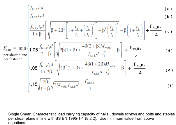
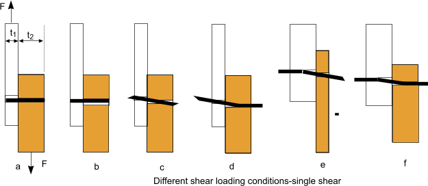
t1 = head side thickness, t2 = point side thickness.


Single Shear :Characteristic load carrying capacity of nails , dowels screws and bolts and staples per shear plane in line with BS EN 1995-1-1 (8,2,2). Use minimum value from above equations.

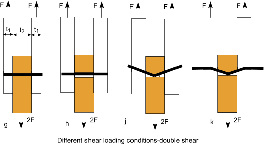
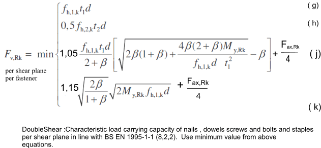
t1 = least of head side thickness and point side,    t2 = central member thickness (in double shear..)

DoubleShear :Characteristic load carrying capacity of nails , dowels screws and bolts and staples per shear plane in line with BS EN 1995-1-1 (8,2,2). Use minimum value from above equations.


Round nails 15%
Square-groved nails 25%
Other nails50%
Screw 100%
Bolts 25%
Dowels 0%


Characteristic Embedment strengths

Nails (not pre-drilled)..fh,k = 0,082 ρkd-0,3 d N/mm2.. Note also applies to screws =< 6mm dia
Nails pre-drilled .. fh,k = = 0,082 (1 - 0,01 d) ρk N/mm2 .... Note also applies to screws > 6mm dia
Bolts /Dowels up to 30mm., Nails and screws over 8mm .
        fh,0,k = = 0,082 (1 - 0,01 d) ρk N/mm2

where
fh,k Embedment strength in N/mm2
ρk = the characteristic timber density in kg/m3
d = nail diameter in mm
fh,0,k Embedment strength with load parallel to grain in N/mm2
fh,α,k Embedment strength with load at angle α to grain in N/mm2
k90 = 1,35 + 0,015d for softwoods / = 1,30 + 0,015d for LVL /= 0,90 + 0,015d for hardwoods


Minimum Edge and Spacing distances


Minimum edge and spacing distances for Bolts...Applicable to screws with d over 6 mm

Spacing and edge distances Angle Minimum spacing or distance
a1 parallel to grain 0o <= α <=360o (4 +|cos α | )d
a2 perpendicular to grain 0o <= α <=360o 4d
a3,t loaded end -90o <= α <=90omax (7d:80mm)
a3,c unloaded end 90o <= α < 150o
150o <= α < 210o
210o <= α <= 270o
max ([1 + 6sin α)d :4d)
4d
max ([1 + 6sin α)d
a4,t loaded edge 0o <= α <=180o max ([2+2sin α)d :3d)
a4,c loaded edge 180o <= α <=360o 3d


Minimum edge and spacing distances for Dowels...

Spacing and edge distances Angle Minimum spacing or distance
a1 parallel to grain 0o <= α <=360o (3 +2.|cos α | )d
a2 perpendicular to grain 0o <= α <=360o 3d
a3,t loaded end -90o <= α <=90omax (7d:80mm)
a3,c unloaded end 90o <= α < 150o
150o <= α < 210o
210o <= α <= 270o
max ([a3,t.sin α)d :3d)
3d
max ([a3,t.sin α)d :3d)
a4,t loaded edge 0o <= α <=180o max ([2+2sin α)d :3d)
a4,c loaded edge 180o <= α <=360o 3d


Minimum edge and spacing distances for Nails......Applicable to screws with d less than 6mm

Spacing and edge distances Angle Minimum spacing or distance
    Without Predrilling Without Predrilling
a1 parallel to grain 0o <= α <=360o (d < 5mm :( 5+5|cos α | )d
d>=5mm :( 5+7|cos α | )d
(7 +8|cos α | )d (4 +|cos α | )d
a2 perpendicular to grain 0o <= α <=360o 5d 7d (4 +|sin α | )d
a3,t loaded end -90o <= α <=90o (10 +5cos α )d (15 +5cos α )d (7 +5cos α )d
a3,c unloaded end 90o <= 270o 10d 15d 7d
a4,t loaded edge 0o <= α <=180o (d < 5mm :( 5+2|cos α | )d
d>=5mm :( 5+5|cos α | )d
(d < 5mm :( 7+2|cos α | )d
d>=5mm :( 7+5|cos α | )d
(d < 5mm :( 3 + 2|cos α | )d
d>=5mm :( 3 + 4|cos α | )d
a4,c loaded edge 180o <= α <=360o 5d <.td> 7d <.td> 3d


Screws

Laterally loaded screws.
The effect of the threaded part of the screw shall be taken into account, when it is taking the shear load by using the effective diameter def.   

When the smooth diameter of the screw penetrates the point side of a joint by more than 4.d then def = the smooth diameter
when this is not the case def = 1,1.thread root diameter

When the screw diameter is greater than 6mm the strength /spacing rules applicable to bolts applies.
When the screw diameter is less/or equal to 6mm the strength /spacing rules rules applicable to nails applies. ..

The embedment strength, connection strength and spacing / distance requirements for screws are shown in the sections above.    Characteristic Embedment strengths..... Edge and distance spacing.....


Axially loaded screws.
For axially loaded screws the evaluation of the resistance of the axially loaded screws should include the following factors

withdrawel failure of the threaded portion of the screw
The tear of failure of the head.( relevant when screw is used to fasten a steel plate.  ( The tear off resistence should exceed the tensile strenth of the screw. )
The pull through failure of the screw head
The tensile failure of the screw
The buckling failure of the screw in compression
Plug shear of the timber associated with a group of screws used with steel plates

minimum edge and end distances and spacings of axially loaded screws are provided in the table below

Min screw spacing in plane parallel to grain Min screw spacing perpendicular to plane parallel to grain Min end distance of c.of g of threaded part of screw Min edge distance of c.of g of threaded part of screw
a1 a2 a3 a2
7d 5d 10d 4d

/p>


where


Nails

Laterally loaded nails.


A nail is either smooth or grooved.
For smooth nails the pointside penetration length should be at least 8d
For nails other than smooth the pointside penetration should be at least 6d
Nails in end grain can not normally be considered as capable of transmitting lateral forces.    Eurocode 5 includes exceptions to this rule para 8.3.1.2(4)


The embedment strength, connection strength and spacing / distance requirements for nails are shown in the sections above.    Characteristic Embedment strengths..... Edge and distance spacing.....


Timber at risk of splitting should be predrilled for nails when
      ...the characteristic density of the timber is more tha 500 kg/m3
      ...the diameter d is greater than 6mm
      ...When the thickness of the timber members is smaller than t = max of { 7d    or     (13d-30)ρk /400   }


As an alternative to this rule the edge distances above may be adjusted such that for ρk <= 420kg/m3 then a4 > = 10 d    and    for    420kg/m3 <= ρk <= 500 kg/m3 then a4 >= 14d.

For one row of nails in a row parallel to the grain ,the load carrying capacity parallel to the grain is

where
FV,ef,RK = Effective characteristic load- carrying capacity of one row of fasteners parallel to the graine
nef = the effective number of fasteners in line parallel to grain
FV,RK = the characteristic load-carrying capacity of each fastener parallel to grain

For nails the effective number of fasteners =

where
n = actual number of nails in row parallel to grain
kef = value give in table below

Spacing spacing kef
not predrilled predrilled
a1 >= 14d 1,0 1,0
a1 = 10d 0,85 0,85
a1 = 7d 0,7 0,7
a1 = 4d - 0,5

Axially Loaded Nails

Only nails which are classified as threaded should be used for withstanding axial loads.

A threaded nail has its shank profiled or deformed over a minimum of 4,5d and has a characteristic withdrawel parameter fax,k greater than or equal to 6 N/mm2 when measure in timber with a characteristic density of 350 kg/m3 at 20degC and 65% humidity

Only the threaded part of the nail is considered capable of transmittting axial loads.

. nails are not capable of transmitting axial loads in endgrain wood

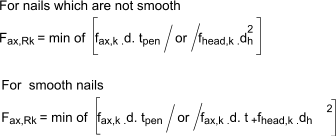
The characteristic withdrawel capacity of nails Fax,Rk for nails driven in perpendicular to grains should be taken as the smaller values from the equations below

where
fax,k = the characterstic pointside withdrawel strength:
fhead,k = the characterstic headside pull-through strength:
d = nail diameter
tpen = the pointside penetration length or the length of the threaded part of the pointside member
t = thickness of headside members
dh = the nail head diameter

Timbers at risk of splitting include douglas fir and Spruce.


Bolts

Laterally loaded bolts

For one row of n bolts parallel to the grain direction, the load-crrying capacity parallel to the grain, should be calculated using the effective number of bolts nef wher

where
d = diameter of bolts
a1 = spacing between bolts in grain directions
n = number of bolts

For loads perpendicular to grain the effective number of bolts =

n ef = n

The embedment strength, connection strength and spacing / distance requirements for bolts are shown in the sections above.    Characteristic Embedment strengths..... Edge and distance spacing.....

Axially loaded bolts

The axial load capacity of a bolt should be taken as the lower value of
    --the bolt tensile capacity
    --the load bearing capacity of either the washer or the steel plate if applicable

The bearing capacity of a washer should be calculated assuming a characteristic compressive strength on the contact area of 3,O fc,90,k

fc,90,k = characteristic compressive strength of timber perpendicular to grain.

The bearing capacity per bolt of a steel plate should not exceed that of a circular washer with a diameter which is the minimum of : 12t or 4d ..(t is thickess of plate and d = diameter of bolt.


Dowels

The various statements applying to bolts as provided above apply except for the spacing and end distances.

The relevant values for end distances and spacings are provided in the section above.i.e Edge and distance spacing.....


Useful relevant Links
  1. Introduction to Structural Timber design to The Eurocodes..Very important document to latest codes :75 page document
  2. EN1995-1-1: Section 8 - Connections.. Extremely useful and informative document.


Structures Index
Timber Design to Eurocodes