Introduction
This page includes notes on design of timber structures and structural components in accordance with the relevant
Eurocode EC 5 (BS EN 1995-1-1: 2004). The notes are outline in nature suitable for enabling basic calculations. For detailed design
it is necessary to refer to the actual standard and all of the associated standards.
Timber construction design to EuroCode 5 is based on limit state design with the two principal catergories being ultimate and seriviceability states.
Ultimate limit state (ULS) = States associated with collapse or similar structural failure.
Serviceability Limit state(SLS) = State such that the structure remains functional for its intended use subject to routine loading.
The durability limit state also needs to be considered . This relates to the risk of
timber decay due to fungal or insect attack as well as the risk of corrosion of metal fasteners and connections.
The requirements of limit state design are identified in Eurocodes Introduction.
The separate catergories of ULS include design for Equilibrium (EQU) = loss of equilibrium of the structure, Strength (STR) Internal failure or
excessive deformation of the structure or structural member, Geology (GEO) = failure due to excessive deformation of the ground, and Fatigue (FAT)
= fatigue failure of the structure or structural members.. The notes on this page relate primarily to the STR Ulitmate limit state category.
Included below are links to timber information pages which are useful but which are not necessarily in accordance
witht the Eurocodes
Almost as important as the design of the timber members is the design of the method of connecting
the timber members.
Outline notes the timber connections in accordance with Eurocode 5 is provided on webpage Timber connections.
An example calculation with equations relating to most of the topics covered on this page is provided ..Example..
Relevant Standards
.
| Code Reference Number | Title |
| BS EN 1990 | Eurocode 0: Basis of structural design |
| BS EN 1995-1-1:2004 | Eurocode 5. Design of timber structures. General. Common rules and rules for buildings |
| BS EN 1995-1-2:2004 | Eurocode 5. Design of timber structures. General. Structural fire design |
symbols
A s = Area of beam
b = breadth of beam
h = height of beam
L = length of member (Eurocode uses  ) )
i = radius of gyration
I = Second Moment of Area
Wy, Wz Elastic modulus about y-y and z-z repectively.
Note for beam below Wy = Iyy /(h/2) and Wz = Izz /(b/2)
Bending
l = span
Md = design moment
G = permanent action
Q = variable action
σm,d = design normal bending stress
fm,k = characteristic bending strength
fm,d = design bending strength
γG = partial coefficient for permanent actions
γQ = partial coefficient for variable actions
γM = partial factor for material properties,modelling uncertainties and geometric variations
kmod = modification factor to strength values, allowing for load duration and moisture content
ksys = load sharing factor
kinst = instability factor for lateral buckling
E0,05 = fifth percentile value of modulus of elasticity
Emean = mean value of modulus of elasticity (parallel) to grain
DEFLECTION:
uinst = instantaneous deformation
uinst,G = instantaneous deformation due to a permanent action G
uinst,Q,1 = instantaneous deformation for the leading variable action Q1
|
ufin = final deformation
ufin,G = final deformation due to a permanent action G
ufin,Q,1 = final deformation for the leading variable action Q1
kdef = deformation factor
wcreep = creep deflection
wc = camber deflection
winst = instantaneous deflection
wnet,fin = net final deflection
wfin = final deflection
um = bending deflection
uv = shear deflection
BEARING:
F90,d = design bearing force
L = length of bearing
σc,90,d = design compression stress
perpendicular to grain
fc,90,k = characteristic compression strength
perpendicular to grain
fc,90,d = design compression strength
perpendicular to grain
COMPRESSION:
L ef effective length of column
λy, λz slenderness ratios about y�y and z�z
axes
λrel,y, λrel,z = relative slenderness ratios about y�y and z�z axes
N = design axial force
σc,0,d = design compression stress parallel to
grain
fc,0,k = characteristic compression strength
parallel to grain
fc,0,d = design compression strength parallel
to grain
σm,y,σm,z,d = design bending stresses parallel to grain
fm,y,d, fm,z,d = design bending strengths parallel to
grain
kc compression factor
|
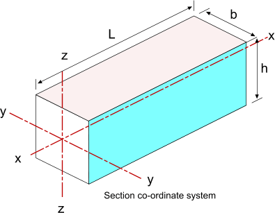
Table of Timber Structural strength class according to BS EN 338 table 1
Important Note; This table is equivalent to the table found in BS 5628 Timber Design however the strength values in this table are
characteristic strengths ( fifth percentile values derived directly from laboratory tests of five minutes ) whereas the equivalent values in
the BS 5628 table are grade stresses which have been reduced for long-term duration and already include a safety factor.
| Species type | Poplar and conifer species | Deciduous species |
| Class | C14 | C16 | C18 | C22 | C24 | C27 | C30 | C35 | C40 | D30 | D35 | D40 | D50 | D60 | D70 |
| Strength properties (N/mm2) |
| Bending fm,k | 14 | 16 | 18 | 22 | 24 | 27 | 30 | 35 | 40 | 30 | 35 | 40 | 50 | 60 | 70 |
| Tension par'l. ft,0,k | 8 | 10 | 11 | 13 | 14 | 16 | 18 | 21 | 24 | 18 | 21 | 24 | 30 | 3642 |
| Tension perp. ft,90,k | 0.3 | 0.3 | 0.3 | 0.3 | 0.4 | 0.4 | 0.4 | 0.4 | 0.4 | 0.6 | 0.6 | 0.6 | 0.6 | 0.7 | 0.9 |
| Compression par'l. fc,0,k | 16 | 17 | 18 | 20 | 21 | 22 | 23 | 25 | 26 | 23 | 25 | 26 | 29 | 32 | 34 |
| Compression perp. fc,90,k | 4.3 | 4.6 | 4.8 | 5.1 | 5.3 | 5.6 | 5.7 | 6.0 | 6.3 | 8.0 | 8.4 | 8.8 | 9.7 | 10.5 | 13.5 |
| Shear fv,k | 1.7 | 1.8 | 2.0 | 2.4 | 2.5 | 2.8 | 3.0 | 3.4 | 3.8 | 3.0 | 3.4 | 3.8 | 4.6 | 5.3 | 6.0 |
| Stiffness properties (kN/mm2) |
Mean modulus of elasticity
parallel E0,mean | 7 | 8 | 9 | 10 | 11 | 12 | 12 | 13 | 14 | 10 | 10 | 11 | 14 | 17 | 20 |
5% modulus of elasticity
parallel E0,05 | 4.7 | 5.4 | 6.0 | 6.7 | 7.4 | 8.0 | 8.0 | 8.7 | 9.4 | 8.0 | 8.7 | 9.4 | 11.8 | 14.3 | 6.8 |
Mean modulus of elasticity
Perpendicular E90,mean | 0.23 | 0.27 | 0.30 | 0.33 | 0.37 | 0.40 | 0.40 | 0.43 | 0.47 | 0.64 | 0.69 | 0.75 | 0.93 | 1.13 | 1.33 |
| Mean shear modulus Gmean | 0.44 | 0.50 | 0.56 | 0.63 | 0.69 | 0.75 | 0.75 | 0.81 | 0.88 | 0.60 | 0.65 | 0.70 | 0.88 | 1.06 | 1.25 |
| Density (kg/m3) |
| Density ρk | 290 | 310 | 320 | 340 | 350 | 370 | 380 | 400 | 420 | 530 | 560 | 590 | 650 | 700 | 900 |
| Average density ρmean | 350 | 370 | 380 | 410 | 420 | 450 | 460 | 480 | 500 | 640 | 670 | 700 | 780 | 840 | 1080 |
The characteristic value for strength as shown in the above table is based a reference depth in
bending and width in tension iof 150mm. For timber
with a depth in bending, or width in tension, less than 150mm the strength is increased in value by a factor kh which
is obtained from the equation

Note: h = the beam depth in bending and the beam width in tension
| Strength Class | Tree Species |
| C14 | Western Red Cedar,Douglas Fir |
| C16 | Hem Fir, |
| C22 | British Pine,spruce |
| C24 | Spruce, Poplar, Larch |
| C30 | Spruce, Poplar, Larch,Pine (redwood) |
| C35 | Douglas Fir |
| D30 | Oak |
| D35 | Beech |
| D40 | Beech, Teak, Eucalyptus |
| D50 | Keruing, Karri, Opepe |
| D60 | Kapur |
| D70 | Balau, Greenheard, Ekki |
Softwood Timber Sizes
Geometrical properties of sawn softwoods
Based on timber with a 20% moisture content
Target
Sizes | Area |
Section Modulus | Section Moment of Area |
Radius of Gyration |
| About x-x | About y-y | About x-x | About y-y |
mm | mm |
| mm | 103mm2 | 103mm3 |
103mm3 | 106mm4 | 106mm4 |
mm | mm |
| 22x100 | 2,20 | 36,6 | 8,1 | 1,83 | 0,089 | 28,9 | 6,35 |
| 38x100 | 3,80 | 63,3 | 24,1 | 3,17 | 0,457 | 28,9 | 11,0 |
| 38x150 | 5,70 | 143 | 36,1 | 10,7 | 0,686 | 43,3 | 11,0 |
| 38x175 | 6,54 | 194 | 42,1 | 17,0 | 0,800 | 50,5 | 11,0 |
| 38x200 | 7,60 | 253 | 48,1 | 25,3 | 0,915 | 57,7 | 11,0 |
| 38x225 | 8,55 | 321 | 54,2 | 36,1 | 1,03 | 65,0 | 11,0 |
| 47x75 | 3,53 | 44,1 | 27,6 | 1,65 | 0,649 | 21,7 | 13,6 |
| 47x100 | 4,70 | 78,3 | 36,8 | 3,92 | 0,865 | 28,9 | 13,6 |
| 47x125 | 5,88 | 122 | 46,0 | 7,65 | 1,08 | 36,1 | 13,6 |
| 47x150 | 7,05 | 176 | 55,2 | 13,2 | 1,30 | 43,3 | 13,6 |
| 47x175 | 8,23 | 240 | 64,4 | 21,0 | 1,51 | 50,5 | 13,6 |
| 47x200 | 9,40 | 313 | 73,6 | 31,3 | 1,73 | 57,7 | 13,6 |
| 47x225 | 10,6 | 397 | 82,8 | 44,6 | 1,95 | 65,0 | 13,6 |
| 47x250 | 11,8 | 490 | 92,0 | 61,2 | 2,16 | 72,2 | 13,6 |
| 47x300 | 14,1 | 705 | 110 | 106 | 2,60 | 86,6 | 13,6 |
| 63x150 | 9,45 | 236 | 99,2 | 17,7 | 3,13 | 43,3 | 18,2 |
| 63x175 | 11,0 | 322 | 116 | 28,1 | 3,65 | 50,5 | 18,2 |
| 63x200 | 12,6 | 420 | 132 | 42,0 | 4,17 | 57,7 | 18,2 |
| 63x225 | 14,2 | 532 | 149 | 59,8 | 4,69 | 65,0 | 18,2 |
| 75x100 | 7,50 | 125 | 93,8 | 6,25 | 3,52 | 28,9 | 21,7 |
| 75x150 | 11,3 | 281 | 141 | 21,1 | 5,27 | 43,3 | 21,7 |
| 75x175 | 13,1 | 383 | 164 | 33,5 | 6,15 | 50,5 | 21,7 |
| 75x200 | 15,0 | 500 | 188 | 50,0 | 7,03 | 57,7 | 21,7 |
| 75x225 | 16,9 | 633 | 211 | 71,2 | 7,91 | 65,0 | 21,7 |
| 75x250 | 18,8 | 781 | 234 | 97,7 | 8,79 | 72,2 | 21,7 |
| 75x300 | 22,5 | 1130 | 281 | 169 | 10,5 | 86,6 | 21,7 |
| 100x100 | 10,0 | 167 | 167 | 8,33 | 8,33 | 28,9 | 28,9 |
| 100x150 | 15,0 | 375 | 250 | 28,1 | 12,5 | 43,3 | 28,9 |
| 100x200 | 20,0 | 667 | 333 | 66,7 | 16,7 | 57,7 | 28,9 |
| 100x225 | 22,5 | 844 | 375 | 94,9 | 18,8 | 65,0 | 28,9 |
| 100x250 | 25,0 | 1010 | 417 | 130 | 20,8 | 72,2 | 28,9 |
| 100x300 | 30,0 | 1500 | 500 | 225 | 25,0 | 86,6 | 28,9 |
| 150x150 | 20,0 | 563 | 563 | 42,2 | 42,2 | 43,3 | 43,3 |
| 150x300 | 30,0 | 2250 | 1130 | 338 | 84,4 | 86,6 | 43,3 |
| 300x300 | 90,0 | 4500 | 4500 | 675 | 675 | 86,6 | 86,6 |
Ultimate limit state design
The principle involved when considering a limit state of rupture or excessive deformation of a section or connection
(STR ) is it shall be verified that :
Ed ≤ Rd
Ed = The design value of the effect of actions such as internal force , moment or
vectorial representation of several internal forces or moments.
Rd = The design value of the corresponding resistance.
In simple English : the value of the product or the maximum expected forces or moments on a section
and the associated partial margins should be less than the characteristic value of the
strength of the sections divided by the relevant material partial safety margins.
Notes on the actions and their associated partial margins are found on this page and notes on the
Resistance values the associated partial margins are found on the web pages related to the construction materials
Serviceability Limit State
Serviceability Limit state(SLS) is the design state such that the structure remains functional for
its intended use subject to routine loading. This affects such situations as doors / windows failing to
open due to structural deformation. It relates to factors others than the building strength that renders
the buildings unusable. Serviceability limit state design of structures includes consideration of
durability, overall stability, fire resistance, deflection, cracking and
excessive vibration. This website only considers this limit state in outline.
Verification for serviceability limit states in the ground or structional section or interface shall
be such that
Ed =< Cd
Cd = Nominal value or function of certain design properties of materials-
(related to serviceability limit state )
In the notes below the sections on deflection and vibration relate to this limit state condition
Design Strength values
The characteristic strengths, Xk, are converted
to design values, Xd, by dividing by a partial factor,
γM and multiplying by a
factor kmod.

Values for these factors are included in the tables below.
Note: γM is not simply a partial factor for
materials but also takes account of modelling and
geometric uncertainties.
kmod = modification factor to strength values, allowing for load duration and moisture content
The eurocode , like BS 5268, allows the design strength determined using equation this be multiplied
by a number of other factors as appropriate such as kcrit , kv , kc,90
and the loading sharing factor, ksys,where several equally spaced similar members are
able to resist a common load. Typical members which fall into this category may include joists in
flat roofs or floors with a maximum span of 6m and wall studs with a maximum height of 4m
The design values for the stiffness are obtained as follows
Ed = Emean / γM
Gd = Gmean / γM
Table for partial factor γM
| Design situation | Partial factor γM
| | Fundamental combinations ... | |
| Solid timber | 1.3 |
| Glued laminated timber | 1.25 |
| Laminated veneer lumber (LVL),plywood, OSB | 1.2 |
| Particle board | 1.3 |
| Fibreboard hard | 1.3 |
| Fibreboard medium | 1.3 |
| Fibreboard, MDF | 1.3 |
| Fibreboard , soft | 1.3 |
| Connections | 1.3 |
| Punched metal plate fasteners | 1.25 |
| Accidental combinations | 1.0 |
| Serviceability limit states | 1.0 |
table for kmod
This is applicable to solid timber , Glued laminated timber, LVL , and Plywood
| Load duration class | Service class |
1 | 2 | 3 |
| Permanent (> 10 years) | 0.60 | 0.60 | 0.50 |
| Long-term (6 months - 10 years ) | 0.70 | 0.70 | 0.55 |
| Medium-term ( 1 week - 6 months) | 0.80 | 0.80 | 0.65 |
| Short-term ( < 1 week) | 0.90 | 0.90 | 0.70 |
| Instantaneous | 1.10 | 1.10 | 0.90 |
examples of loading duration assignment are provided below
permanent : self weight
long term : storage
medium term : imposed floor load, snow
short term : snow , wind
instantaneous: wind , accidental load
|
System strength
When the design loads are carried by several equally spaced and similar members which are
connected laterally by a continuous load distribution system, the member strength properties may be
multiplied by a system strength factor ksysof 1,1
Service Class
Moisture has a significant effect on the mechanical properties of timber and the British standard allocates service class
designations to allow for this
The permissible stresses used is generally alocated relevant
to the service classes as identified below. This is the same for Eurocode 5 as for BS 5268.
Service classes ( based on clause 2.3.1.3, BS EN 1995 )
a) Service class 1 is characterized by a moisture content in the materials corresponding to a temperature
of 20 �C and the relative humidity of the surrounding air only exceeding 65 % for a few weeks per year.
In such moisture conditions most timber will attain an average moisture content not exceeding 12 %.
b) Service class 2 is characterized by a moisture content in the materials corresponding to a temperature
of 20 �C and the relative humidity of the surrounding air only exceeding 85 % for a few weeks per year.
In such moisture conditions most timber will attain an average moisture content not exceeding 20 %.
c) Service class 3, due to climatic conditions, is characterized by higher moisture contents than service
class 2.
Note: Design using timber sections greater than 100 thick or deep are generally based on service class 3 because of the difficulty
in drying thicker sections.
Design Resistance
The design value of a resistance ( load carrying capacity ) ,Rd , is calculated as

Rk = characteristic load carrying capacity
γM = the partial factor for a material property
kmod = modification factor taking into account the effect of load duration and moisture content
Actions
The actions on a structure or a structural element comprise of permanent actions which are in principle unchanging through the
life of the structure and variable actions which are not fixed. The prime example of a permanent action is the weight of the construction
materials. Examples of variable actions include wind loading, occupancy loading, storage loading.
As noted on the webpage Eurocodes Introduction,
the design value of an action (Fd) is obtained by multiplying the representative value (Frep) by
the appropriate partial safety factor for actions (γf):
Fd = γf.Frep
where
F rep is the representative value of an action. This is generally equal to the characteristic F k value of an permanent action
or the leading variable action value , or it is equal to the ψ. F k of an imposed ( variable action ).
γ F is the partial factor for an action ( or γ E , for the effect of an action ).
..Fk = Gk and
γ F = γ G for a permament action.
..Fk = Qk and
γ F = γ Q for an imposed action.
The general equation for the effect of actions should be

The part of the equation inside the brackets represents the combination of permanent and variable actions
In BS EN 1990 one of a number of equations for action (load ) combinations is equation 6,10
This is a quick, but conservative, method when compared to the alternative equations ( 6.10a and 6.10b )which are a little more complicated.
6.10b is generally the governing equation in the UK
| Persistent and transient design situations | permanent actions |
Leading variable actions | Accompanying variable actions |
| Unfavourable | Favourable | Unfavourable | Favourable | Main (if any |
Others |
| BS EN 1990(eq 6.10) |
γG.j,supGk,j,sup |
γGj,infGk,j,inf |
γQ,1Qk,1 |
- |
γQ,i ψ0,1 Qk,i |
| Combination of permanent and variable action ( Strength limit States STR ) |
| BS EN 1990(eq 6.10) |
1,35Gk |
1,0Gk |
1,5Qk.1 |
0 |
- | - |
| Combination of permanent and variable action and accompanying variable action ( Strength limit States STR ) |
| BS EN 1990(eq 6.10) |
1,35Gk |
1,0Gk |
1,5Qk.1 |
0 |
- |
1,5 ψ0.1 Qk.1 |
| Combination of permanent and variable action and accompanying variable action ( Equilibrium limit States EQU ) |
| BS EN 1990(eq 6.10) |
1,1 Gk |
0,9 Gk |
1,5Qk.1 |
0 |
- | 1,5 ψ0.1 Qk.1 |
Design of colums subject to compression or combined compression and bending.
Note: Basic information on columns and struts and the derivation of the buckling equations if found at Struts
The slenderness ratio is simply defined as the
λ = Length ( Effective Length = Le) / radius of Gyration = k.
The relative slenderness ratios are obtained from

Where both λrel,z and λrel,y ≤ 0,3
the stress should satisfy the conditions for combined bending and compression as identified below.
In all other cases the stress which should increase resulting from deflection should satisfy the following
expressions.
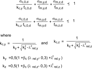
Combined bending and axial compression
for timber memebers ubject to combined bending and axial compression the following condiions should be satisfied
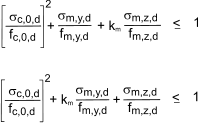
Design of flexural members
The design of flexural members principally involves
consideration of the following actions which are
discussed next:
1. Bending
2. Lateral buckling
3. Shear
4. Bearing
5. Torsion
6. Deflection
7. Vibration
BENDING
If members are not to fail in bending, the following
conditions should be satisfied:
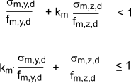
σm,y,d and σm,z,d = the design bending stresses
and about axes y�y and z�z
fm,y,d and fm,z,d = the corresponding design bending
strengths
km = a factor that allows for the
redistribution of secondary bending
stresses and assumes the following
values:
� for rectangular or square sections;
km = 0.7
� for other cross-sections;
km = 1.0
As an example for a rectangular section beam of width b and height h

My,d = Bending moment about y-y
Wy = elastic modulus about y-y = Iyy /( h/2)
Lateral Buckling
A beam is not be at risk of buckling under axial compressive loading if lateral
displacement and rotation is prevented along its length along its length. Otherwise the
member may be vulnerable to lateral buckling and
the rules in provide in BS EN 1995-1-1 should be used
to assess the bending behaviour. Generally, the following
condition should be verified

σm,d design bending stress
fm,d design bending strength
kcrit is a factor which takes into account the
reduction in bending strength due to lateral
buckling and is given by
kcrit = 1 for λrel,m = < 0.75
kcrit = 1.56 - 0.75 . λrel,m for 0.75 < λrel,m = < 1.4
kcrit = 1 / λrel,m2
for 1.4 < λrel,m
where < λrel,m is the relative slenderness ratio for
bending given by

where
fm,k is the characteristic bending stress
σm,crit is the critical bending stress generally

Note: for softwoods with solid rectangular sections the following can be assumed

where
Lef = the effective length of the beam, reference table below.
b = width of beam
h = depth of beam
Iz = the second moment of area about z-z
Itor = the torsional moment of inertia
fm,k = characteristic bending strength
E0,05 = the fifth percentile modulus of elasticity
parallel to grain
G0,05 = the fifth percentile shear modulus = E0,mean/16
Wy = Elastic modulus about y-y.
| Beam type | Loading type | Lef / L |
| Simply supported | Constant moment | 1.0 |
| Uniformly distributed load | 0.9 |
| Concentrated force at the middle of the span | 0.8 |
| Cantilever | Uniformly distributed load | 0.5 |
| Concentrated force at the free end | 0.8 |
Note; table only applies if compression load is on centre of gravity of section on torsionally restrained beams.
SHEAR
Reference Shear stress
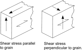
For shear with a stress component parallel to the grain as well as for shear with
both components perpendicular to the grain.
If flexural members are not to fail in shear, the
following condition should be satisfied:
τ d < = fv,d
where
τ d is the design shear stress
fv,d is the design shear strength
For a beam with a rectangular cross-section, the
design shear stress occurs at the neutral axis and is
given by:

where
VEd = the design shear force
A = the cross-sectional area
The design shear strength, fv,d is given by

where
fv,k = the characteristic shear strength
Note: The shear strength for rolling shear is approximately twice the tensile strength perpendicular to the grain.
For beams notched at their ends as shown in figure below the following condition should be
checked


kv is the shear factor which may attain the following
values:
For beams notched at the opposite side to support
kv = 1
For beams of solid timber notched at the same
side as support

where
kn = 5 for solid timber , = 4,5 for LVL, = 6,5 for glued laminated timber
i = the notched inclination as defined in figure
h = s the beam depth in mm
x = the distance from line of action to the corner

BEAMS SUBJECT TO LATERAL COMPRESSION
For compression perpendicular to the grain the
following condition should be satisfied:
σc,90,d <= kc,90 fc,90,d
where
σc,90,d = the design compressive stress
perpendicular to grain
fc,90,d = the design compressive strength
perpendicular to grain
kc,90 = the compressive strength factor allowing for load configuration/ risk of splitting/degree of compressive deformation

where
Fc,90,d = the design compressive load perpendicular to grain
Aef = Effective contact area in compression perpendicular to grain

The effective contact area, Aef , is determined using an effective length based on the
actual contact length at each side which is increased by 30mm but not more than a1, L or L1/2
(refer to figure above )
kc,90 should be taken as 1 unless the conditions below apply.
For beams on continuous supports and providing L1 >= 2h then
kc,90 = 1,25 for solid softwood timber
kc,90 = 1,5 for glued laminated timber
For beams on discrete supports and providing L1 >= 2h then
kc,90 = 1,5 for solid softwood timber
kc,90 = 1,75 for glued laminated timber providing L <= 400mm
TORSION
For beams subject to torsion the following expression shall be satisfied

where
kshape = 1,2 for circular sections
kshape = The lesser of
1+0,15.h/b or
2,0
for rectangular sections.
τ tor,d = design torsional stress;
fv,d = design shear strength;
kshape = factor depending on shape of cross-section;
h = larger cross section demensions
b = smaller cross section dimension
DEFLECTION
BS EN 1995 recommends various limiting values of deflection for beams. The
symbols relating to the deflection are shown in figure below.. I am using L not l to avoid it looking like number 1.
Note: Deflection and and vibration are generally most relevant for Design to serviceability limit states..

wcreep = creep deflection
wc = camber deflection
winst = instantaneous deflection
wnet,fin = is the net final deflection due to permanent
and variable actions = wfin - wc
wfin = final deflection due to permanent and variable actions = winst + wcreep
um = bending deflection
uv = shear deflection
Examples of limiting values of defelection based on BS EN1995-1-1 table 7,2
| Description | w inst | w net.fin | w fin |
| Beam with span (L) between 2 supports | L/300- L/500 | L/250 to L/350 | L/150 to L/300 |
| Cantilever Beam | L/150- L/250 | L/125 to L/175 | L/75 to L/150 |
Specific limiting values for deflections of beams ( based on Table 4 of NA to EN 1995)
| Description | limit of deflection w fin |
| member with span (L) between 2 supports | A cantilerver of length (L) |
| Roof of floor members with a plastered or plasterboard ceiling | L/250 | L/125 |
| Roof of floor members without a plastered or plasterboard | L/150 | L/75 |
Eurocode 5 includes consideration for the load duration and moisture influences on deformations having time-dependent properties i.e creep.
The final mean modulus of elasticity and shear modulus used to calculate deflections are obtained using the following equations.
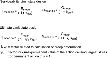
table for kdef
| Load duration class | Service class |
1 | 2 | 3 |
| Solid Timber. EN 14081-1 | 0.60 | 0.80 | 2,00 |
| Glued laminated timber./ EN 14080 | 0.60 | 0.80 | 2,00 |
| LVL. EN 14374, EN 14279 | 0.60 | 0.80 | 2,00 |
| Plywood type EN636-1 | 0.80 | - | - |
| OSB. EN 312 OSB/2 | 2,25 | - | - |
| Particleboard EN312 Type P4 | 2,25 | - | - |
| Fibreboard hard. EN 622-2 HB0LA | 2,25 | - | - |
| Fibreboard med. EN 622-3 MBH-LA1, MBH.LA2 | 3,00 | - | - |
| Fibreboard MDF EN 622-5 MDF-LA | 2,25 | - | - |
VIBRATION
BS EN 1995 includes a requirement for the serviceability limit state design
that the actions on a member or a structure do not result in vibration levels which are
are not acceptable for functional and occupier comfort and safety levels. The notes below identify
the requirements for an acceptable level of imposed structural vibration.
The fundamental frequency of vibration of a
rectangular residential floor, f1, is estimated
using the following eqaution and should normally
exceed 8 Hz.

m = mass equal to the self weight of the floor
and other permanent actions per unit area in kg m-2
L = floor span in m
(EI)L = equivalent bending stiffness in the beam direction N.m2 / m.
For cases when the fundemental frequency of the floor exceeds 8 Hz the following additional requirements are imposed
by the code.

ξ = modal damping coefficient, normally taken as 0.02
ω = maximum vertical deflection caused by a concentrated static force F = 1.0
ν = unit impulse velocity
a = is the deflection of floor under a 1 kN point load .
a must not exceed 1,8mm for L <= 4 000mm
a must not exceed 16 500/ L 1,1 mm for L > 4 000mm
b = is the velocity response constant .
b = 180 - 60.a if a <= 1mm
b = 160 - 40.a if a > 1mm
ω may be estimated from the equation< below

kdist is the proportion of point load acting on a single joist
leq is the equivalent floor span in mm
kamp is the amplification factor to account for shear deflection in the case of solid timber
(EI)joist is the bending stiffness of a joist in N.mm2 (calculated using Emean)

kstrut = 0.97 for appropriately installed single or multiple lines of strutting, or otherwise 1.0
(EI)b is the floor flexural rigidity perpendicular
to the joists in N mm2 / m
s is the joist spacing in mm
Leq is the span, in mm, for simply supported single span joists
kamp 1.05 for simply supported solid timber joists
The value of ν may be estimated from

b is the floor width in m
L is the floor length in m
n40 is the number of first order modes with natural frequencies below 40 Hz and is given by

where (EI)L is the equivalent plate bending stiffness
parallel to the beams and the other symbols are as
defined above.
|


