| |
Fluids Index Forces resulting from fluid momentum and Thrust by reaction.
Introduction..... Symbols..... Momentum Notes..... Stationary Plates..... Moving Plates..... Vanes..... Pipe walls.....
|
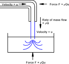
Introduction The study of forces resulting from the impact of fluid jets and when fluids are diverted round pipe bends involves the application of newtons second law in the form of F = m.a. The forces are determined by calculating the change of momentum of the flowing fluids. In nature these forces manifest themselves in the form of wind forces, and the impact forces of the sea on the harbour walls. The operation of hydro-kinetic machines such as turbines depends on forces developed through changing the momentum of flowing fluids. I have created a excelcalcs spreadsheet for convenient access to all of the equations found on this page . This is located at ExcelCalcs.com calculation Fluid Jets Symbols
Momentum Newtons Second Law can be stated as: The force acting on a body
in a fixed direction is equal to rate of increase of momentum of the body
in that direction. Force and momentum are vector quantities so the direction
is important. A fluid is essentially a collection of particles and the net force, in a fixed direction,
on a defined quantity of fluid equals the total rate of momentum of that fluid quantity
in that direction. The figure below illustrates this principle at two locations.
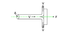
In its simplest form, with steady flow conditions, the force on a fluid flow in a set direction is equal to its mass flow rate times by the change in velocity in the set direction. The fluid flow also exerts an equal and opposite reaction force as a result of this change in momentum. F = Qρ (u 1 - u 2). ..( F and u are vector quantities) The resultant force on a fluid in a particular direction is equal to the rate of increase of momentum in that direction. Jet Forces on Stationary Plates Jet force on a flat plate
Considering only forces in a horizontal direction u 1 = V and u 2 = 0 therefore Jet force on a flat plate at an angle θ
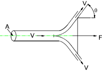
Considering only forces Normal to plate surface u 1 = V sinθ and u 2 = 0 therefore Jet force on an angled plate. (θ < 90 o)
Considering only forces in a horizontal direction u 1 = V and
u 2 = V cos θ therefore Jet Force on an angled plate (θ > 90 o)
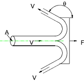
Considering only forces in a horizontal direction
u 1 = V and
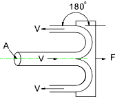
u 2 = V cos θ therefore Jet Force on an angled plate (θ = 180 o)
u 1 = V and
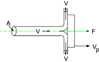
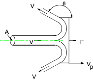
u 2 = V cos θ therefore Jet Forces on Moving Plates......Fluid Machines - Pelton Wheel Jet force on a moving flat plate
Considering only forces in a horizontal direction Jet force on an angled moving plate
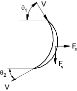
Considering only forces in a horizontal direction Jet Forces on Vanes...... Additional notes can be found on webpages Force on fixed Vane.
In the x Direction: u 1x = V cos θ 1 ,
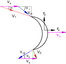
u 2x = -V cos θ 2 Force on Moving Vane. The notes below related to vanes as used in impulse turbines. These turbines derive the mechanical energy mainly from the change in momentum as the fluid passes through the vanes. The conditions as shown when the vectorial sum of V v + V r1 = V1 results in smooth entry with efficient transfer of energy of the fluid to the vane. When this does not occur there will be turbulent flow over the vane with significant losses.
In the x Direction Force on Pipe Wall The notes below related to the force on a pipe wall resulting from the changes in fluid pressure and fluid momentum as the fluid flows round a pipe bend . Gravity and friction effects are not considered. The fluid is assumed to be flowing under steady state conditions.
In the x Direction
The resultant reaction force on the pipe = Fr =√ (Fx2 + Fx2 ) |
Useful Links
|
|
Fluids Index
