Introduction
The fluid machines covered on this page are primarily hydraulic machines.
The notes below only relate to the general principles involved - more specific notes and information on steam
and pneumatic machines, are provided on the linked pages below.
A fluid machine is a device for
converting energy held in a fluid ( dynamic or potential ) into mechanical energy or
it can convert mechanical energy into fluid based energy.
Notes on Pump Types and Operation
Notes on Air Compressors and Motors
Notes on Steam Turbines
Notes on pneumatics and hydraulics
The main types of fluid machines are listed as
Turbines and pumps..
A turbine directly converts fluid energy into
rotating shaft energy.
If the fluid motion is converted, initially to reciprocating mechanical motion the machine is an engine e.g and
internal combustion engine or a steam engine ).
A machine for converting mechanical
energy into fluid flow is called a pump...
Compressors or Fan ..
If the machine converts mechanical energy to increase the potential energy of
a compressible fluid by increasing its pressure the machine is called a compressor. If
the machine is primarily provided to increase the kinetic energy of a compressible fluid e.g. air,
the machine is a fan. With a fan or blower the pressure head developed is usually relatively
small and fluid calculations can often be done assuming the fluid is incompressible.
Positive Displacement Machines ..
A pump can be a positive displacement machine or a rotodynamic machine Ref. Pumps ..Positive displacement
machines are designed such that there is virtually zero fluid slippage
in the energy transfer process. The general principle of these type of
pumps is that fluid is drawn into a chamber at a low pressure. The inlet to the chamber is
closed and the outlet is opened, and the fluid is then forced out of the chamber by reducing its volume.
The type of pump can be used to generate very high pressures in a compact mechanical envelope. The main
disadvantage is that the operation is an intermittent one resulting in a high level of pressure fluctuation throughout
the operating cycle.
Rotodynamic Machines ..
All rotodynamic machines have a rotating component through which the fluid
passes. In a turbine this is called the rotor which has a number of vanes or blades.
The fluid passes through the blades and drives the rotor round transferring tangential
momentum to the rotor. In a pump the tangential motion of the rotor as it
rotates results in an increase in the tangential momentum of the fluid .
This increase in kinetic energy is converted to pressure by decelerating the fluid in
the discharge route from the pump. In a turbine the fluid passes over /through
the impeller and loses energy (momentum and pressure) the energy being transferred to
the rotor.
Rotodynamic machines are smooth and continuous in action with a consequent pulsation free
flow from pumps and smooth rotation from turbines. In the event of pump discharge
flow being suddenly stopped there are no high shock loads. Positive displacement machines
can easily be damaged if a discharge valve is suddenly closed. Rotodynamic
pumps are ideal for high flow low discharge head duties and provide compact reliable solutions.
Symbols
A = Area (m2)
a = Speed of sound (m/s)
CV = Coefficient of Velocity for nozzle.
ρ = density (kg/m3)
ρ1 = density at inlet conditions(kg/m3)
g = acceleration due to gravity (m/s2 )
ε = Expansion factor
h = fluid head (m)
L = Pipe length (m )
m = mass (kg)
m = mass flow rate (kg/s)..
P1 = Inlet fluid pressure (gauge) (N /m2 )
P2 = Outlet fluid pressure (gauge) (N /m2 )
P1 = Inlet fluid pressure (abs) (N /m2 )
P2 = Outlet fluid pressure (abs) (N /m2 )
P - Absolute pressure (N /m2 )
pgauge - gauge pressure (N /m2 )
patm - atmospheric pressure (N /m2 )
|
p s= surface pressure (N /m2 )
Q = Volume flow rate (m3 /s)
Qm = Mass flow rate = Qρ (kg /s)
Re = Reynolds Number = u.ρD/μ
r = Turbine wheel radius (m)
u1 = initial fluid velocity (m/s)
u2 = final fluid velocity (m/s)
uW1 =initial fluid whirl velocity (m/s)
uW2 =final fluid whirl velocity (m/s)
VB = Bucket velocity (m/s)
VR1 = Inlet Fluid Velocity relative to bucket(m/s)
w = Turbine shaft work / unit mass flow rate (Nm /(kg/s)
θ =slope (radians)
μ = viscosity (Pa.s)
ν = kinematic viscosity (m2�s-1)
υ = Specific volume (m3 / kg)
γ= Ratio of Specific Heats
ω = Angular Velocity of wheel ( radians /s)
|
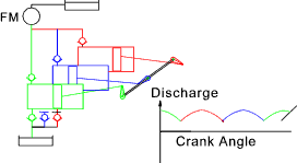
Reciprocating Pumps
The general principles of operation of the reciprocating pump is
illustrated by the figure below. The motion of the piston is such that
it is driving the fluid out of the cylinder through the one way valve into the upper tank.
The fluid, in this case, is incompressible and the flow rate is almost totally dependent on the velocity of
the piston. As the driving arm continues to rotate the piston commences to move outwards. Reverse flow
in the discharge line results in the discharge valve closing and fluid being drawn up from
the lower reservoir causes the suction valve to open. Fluid is therefore drawn into the cylinder
from the lower reservoir.
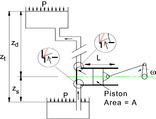
The design of the inlet and outlet valves as shown are simple flap
valves. Other valve types include ball valves and poppet valves. The valves
may be gravity/flow operated or spring operated or mechanically linked to the position of the
piston.
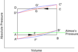
A plot showing the absolute pressure against piston displacment volume is
shown above. The piston has an area A and the pressure within the cylinder is p.
The work done by the piston in the discharge stroke and on the piston in the suction stroke is F dx. = p A dx. = p dV.
The area enclosed within the pressure- volume curve therefore represents the work done by
the cylinder in one cycle.
A-B-C-D represents the operating cycle with no losses. A'-F-B'-C'-G-D' is the curve allowing
for the inertia of the fluid i.e. the fluid has to be accelerated and the start of the stroke and slowed
at the end of the stroke. A'-F'-B'-C'-G'-D' also includes for the friction in the piping and the
inlet and outlet valves- this will be greatest at the middle of the stroke when the velocity of the piston is
highest ( due to the motion of the driving arm). Note: the differences
between the ideal and real plots are exaggerated. The deviations from the no-loss operating cycles are clearly more
pronounced as the pump speed increases
The design of the valves can have a significant effect on the efficiency
of operation of the piston pump. Some systems have valves which are large compared to the
volume of the cylinders. Spring loaded lift valves working at relatively high frequencies
can bounce and the effect on the operating curve can be significant as shown in the figure above.
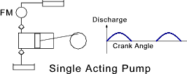
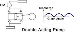
The motion of the piston (plunger) and consequently the output flow is sinusoidal. In practice
it is desirable to have a smooth continuous flow. There are a number of methods of increasing the
delivered flow including. Using double acting pumps and using mult-cylinder pumps. These arrangements
are shown below.
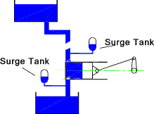
The inflows and the outflows can be further smoothed and the pulsations can be
largely eliminated by installing surge tanks as shown below
In practice the discharge resulting from each cycle is slightly different
from the volume displaced by the piston (plunger). This is because a certain
leakage takes place and the valves do not open and close instantly. This is identified
by using a coefficient of discharge. The coefficient of discharg Cd
is the Discharge per cycle / The Swept volume. The percentage slip is also used
to identify this source of inefficiency.
% Slip = 100 .(1 - Cd ) = 100 {[ Swept Volume - Discharge volume/stroke] / Swept Volume }
Turbines
Unlike the reciprocating positive displacement pumps,
which work primarily under hydrostatic conditions, turbines transfer
energy to the fluid under hydrodynamic conditions by converting the kinetic energy
of the blades to kinetic energy of the fluid or vice versa. In radial flow
machines the fluid flows mainly in the plane of the rotation. The fluid enters
the machine at one radius and exits the machine at a different radius. This type of machine includes the
Francis turbine and the centrifugal pump. In axial flow machines the fluid moves
generally parallel to the axis of the pumps. If the flow is partly radial and partly axial
the machine is said to be a mixed flow machine. A rotodynamic pump can often be used
as a motor. This option is often used for hydraulic pump storage systems
For any turbine the energy in the fluid is initially pressure energy.
For water turbines, this pressure energy is developed as a head of fluid in a high
level reservoir. For steam turbines the pressure is developed by the addition of heat in boilers..
The impulse turbine has one or more fixed nozzles. The nozzles turn the pressure energy
into kinetic energy as high velocity jets of fluid. These jets then impinge on the moving
blades of the runner where the fluid loses almost all of its kinetic energy and the momentum is transferred
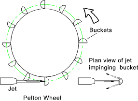
to the blade. A typical impulse turbine is the pelton wheel
The reaction turbine fluid transfers its energy by tangential slippage across the blades literally pushing the blades
sideways out of its path. The energy transfer is a gradual process, the fluid loses it kinetic energy
progressively. The fluid literally fills all of the passages through turbine blades. A typical reaction
turbine is the steam or gas turbine.
Impulse Turbines - Pelton Wheel....
Reference Jets on moving plates
In a typical pelton wheel, as shown, below the fluid kinetic energy is transferred to the rotating wheel according to the momentum equation. The fluid velocity,
momentum, and the resulting force on the buckets are all vector quantities and the system is best
analysed using vectors.
The velocity of the fluid leaving the jet is given by

CV = coefficient of velocity (between 0,97 and 0,99)
H is the net head at the nozzle = (HT - Hf)= (the total head due gravity - The friction head which is generally negligible.)
The vector diagram for the fluid impinging on the bucket is shown below. Each bucket rotates
slightly while it is in the path of the jet but this does not have a significant effect on the
analysis.
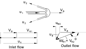
The outlet flow flow from the bucket is split but the split is considered symmetrical and
therefore one path only needs to be considered.
The velocity of the fluid approaching the bucket = u1.
The velocity of the bucket = VB.
The velocity of the approaching fluid to relative the bucket velocity is VR1 = u1 - VB
The velocity of the outlet fluid relative the bucket velocity is VR2 = k.VR1 (k being a friction loss factor)
The velocity of the fluid in the direction of bucket movement -> is the whirl velocity.
The inlet whirl velocity = u1
The outlet whirl velocity uw2 is simply VB - VR2(cos (π - θ)
The radius of the wheel is r.
The change in whirl component of the fluid velocity
= ΔuW
= u1 - [VB-VR2 (cos (π - θ)]
= VR1 - k.VR1cos (π - θ)
Therefore..

The force( F )driving the bucket round is equal to the rate of change of momentum of the fluid F = ρ QΔuW.
The torque driving the wheel = F r
The power from the wheel is F r ω = Q ρ ΔuW VB
The rate of kinetic energy arrival in the fluid = [ Q ρ u 12 ] /2
The efficiency of the Pelton Wheel is therefore expressed as follows
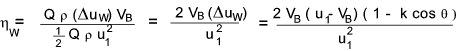
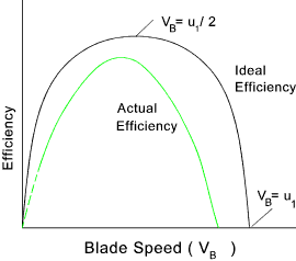
It can be easily proved that the maximum efficiency
of the Pelton wheel is when VB = u1 / 2...
(Assuming the friction factor is constant ).
The above analysis is an idealised one. In practice there will be friction losses reflect in the value
of k. There will be losses as the buckets move into and out of the line of the jet, and
there will be windage losses as the wheel rotates. The graph below shows the effect
of these losses on the efficiency curve
The principle methods of controlling the speed of the Pelton wheels is by using
special valves associated with the nozzles or by diverting the jet away from the buckets or
by simply starting and stopping the flow.
Pelton wheels are more suitable for operating under large heads...
Further notes on impulse turbines as related to steam as a fluid are found at Steam Turbines -Impulse Blading
Reaction Turbines - Francis Turbine - Centrifugal Pump ....
The reaction turbine is completely immersed in the fluid and the energy is converted from
fluid to mechanical motion , and vice versa, gradually as the fluid passes over the blades.
In a reaction turbine the fluid (water) supplied to the rotor (runner) possesses part pressure
energy and part and kinetic energy . Both types of energy ar converted into work in the runner, resulting
in a drop of the pressure and absolute velocity of the fluid. A typical
reaction turbine is the Francis Turbine which is generally arranged with a vertical shaft.
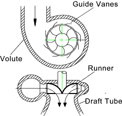
This type of turbine is a mixed flow type - the fluid entering the runner in a radial direction
and exiting the runner axially downwards.
The only movement of the runner blades is in the circumferential direction and therefore
only circumferential fluid force components result in work transfer.
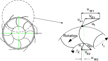
The fluid velocity at the feed into the rotor tangential to the rotor is uW1.
The fluid velocity leaving the rotor in the tangential direction is uW2.
Considering a particle
of fluid δm at the rotor inlet . This has a tangential momentum
uW1 δm and an angular momentum uW1 r1 δm.
The mass particle has a angular momentum on leaving the rotor of uW2 r2 δm.
If the total mass flow rate is m and considering a small part of this flow δm.
The rate of momentum entering the rotor is uW1 r1 δm and the rate of momentum leaving the rotor
is uW2 r2 δm. This assumes r1 , r2, uW1 and uW2
are constant over the area over which δm flows.
The total rate of fluid momentum loss across the turbine is equal to the torque acting on the fluid which is
By application of Newtons third law ( for revery action there is a equal and opposit
reaction) the fluid exerts the same torque , in reverse on the rotors.
The above equation is known as Euler's equation and identifies a fundamental relationship
for all forms of rotodynamic machinery including turbines, pumps, fans and compressors. It applies to
rotors and stators.
If the products uW1 r1 and uW2 r2 are each constant at the inlet and
outlets (vortex free) then the equation simplifies to

If the value of Tr is positive and the rotor is rotating in the same
direction as the fluid then the fluid does work on the rotor and the machine is
operating as a turbine.
If the fluid resists rotation of the rotor or impeller and Tr from the above equation is negative then
the machine is operating as a pump.
The rate at which shaft work is done on the rotor (power) is Tω .
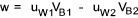
Now if the turbine shaft work rate is divided by the mass flow rate
the work done per unit mass ( w ) results
Referring to the figure below the net Head (H) across the Francis machine is the total
head between the supply reservoir and the tail water , minus the pipe friction losses (hf ) and the
kinetic head of the fluid at outlet of the draft tube. Therefore
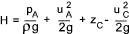
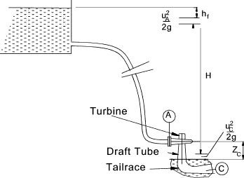
The energy available per unit mass = Hg
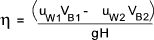
Therefore the efficiency of the Francis Turbine is
|