Thermos Index Thermodynamics-Steam Turbine
Introduction..... Principles...... Impulse Turbines...... Reaction Turbines...... Rankine Cycle...... Turbine Enthalpy Cycle......
|
Introduction A steam turbine is a mechanical device that converts thermal energy
in pressurised steam into useful mechanical work. The original steam engine which largely
powered the industrial revolution in the UK was based on reciprocating pistons.
This has now been almost totally replaced by the steam turbine because the steam turbine
has a higher thermodynamic efficiency and a lower power-to-weight ratio and the steam
turbine is ideal for the very large power configurations used in power stations.
The steam turbine derives much of its better thermodynamic efficiency because of the
use of multiple stages in the expansion of the steam. This results in a closer approach to the
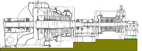
ideal reversible process. Steam Turbine Principle The steam energy is converted mechanical work by expansion through the turbine. Th expansion takes
place through a series of fixed blades (nozzles) and moving blades each row of fixed blades and
moving blades is called a stage. The moving blades rotate on the central turbine rotor and the fixed blades
are concentrically arranged within the circular turbine casing which is substantially designed to withstand the steam
pressure.
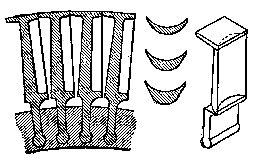
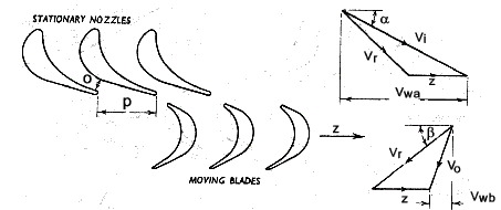
There are two principles used for design of turbine blades the impulse blading and the reaction blading. The impulse blading principle is that the steam is directed at the blades and the impact of
the steam on the blades drives them round. The day to day example of this
principle is the pelton wheel.ref Turbines.
z represents the blade speed , V r represents
the relative velocity, V wa & V wb- represents the
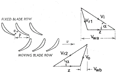
tangential component of the absolute steam in and steam out velocities Power /stage= (V w a + V wb).z/1000 kW per kg/s of steam Reaction Blading The reaction blading principle depends on the blade diverting the steam flow and gaining kinetic energy by the reaction. The Catherine wheel (firework) is an example of this principle. FOr this turbine principle the steam pressure drop is divide between the fixed and moving blades.
z represents the blade speed , V r represents
the relative velocity, V wa & V wb- represents the
tangential component of the absolute steam in and steam out velocities Power /stage= (V w a + V wb).z/1000 kW per kg/s of steam The blade speed z is limited by the mechanical design and material constraints of the blades. Rankine Cycle The Rankine cycle is a steam cycle for a steam plant operating under the best theoretical conditions
for most efficient operation. This is an ideal imaginary cycle against which all other
real steam working cycles can be compared.
The ratio output work / Input by heat transfer is the thermal efficiency of the Rankine cycle and is expressed as
Although the theoretical best efficiency for any cycle is the Carnot Cycle the Rankine cycle provides a more practical ideal cycle for the comparision of steam power cycles ( and similar cycles ). The efficiencies of working steam plant are determined by use of the Rankine cycle by use of the relative efficiency or efficiency ratio as below:
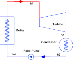
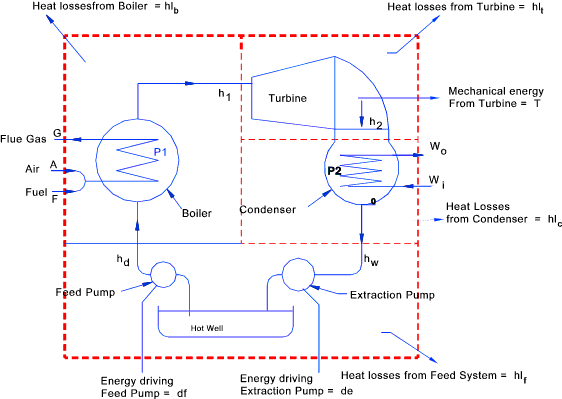
The various energy streams flowing in a simple steam turbine system as indicated in the diagram below.
It is clear that the working fluid is in a closed circuit apart from the free surface of the hot well. Every
time the working fluid flows at a uniform rate around the circuit it experiences a series of
processes making up a thermodynamic cycle.
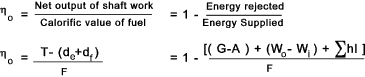
Boiler F + A + h d = h 1 + G + hl b hence F + A = G + h 1 - h d + hl b Turbine h 1 = T + h 2 + hl t hence 0 = T - h 1 + h 2 + hl t Condenser Unit W i + h 2 = W o + h w + hl c hence W i = W o + h w - h 2 + hl c Feed Water System h w + d e + d f= h d + hl f hence d e + d f = - h w + h d + hl The four equations on the right can be arranged to give the energy equation for the whole turbine system enclosed by the outer boundary
That is ..per unit mass the of working agent (water) the energy of the fuel (F) is equal to the sum of
- the mechanical energy available from the turbine less that used to drive the pumps
(T - (d e+ d f) The overall thermal efficiency of a steam turbine plant can be represented by the ratio of the net mechanical energy available to the energy within the fuel supplied. as indicated in the expressions below...
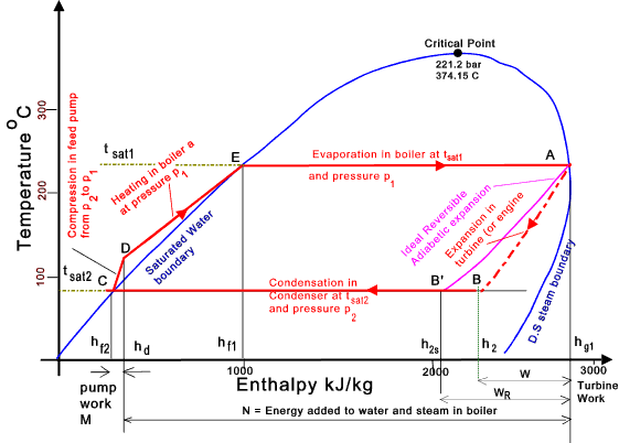
Turbine Vapour Cycle on T-h Diagram
This cycle shows the stages of operation in a turbine plant. The enthalpy reduction
in the turbine is represented by A -> B . The reversible process for an ideal isentropic (reversible adiabetic)
is represented by A->B'. This enthalpy loss would be (h g1 - h 2 ) in the reversible case
this would be (h g1 - h 2s ).
|
Steam Turbine Links
|
|
Thermos Index