Introduction
The notes on this page related to the methods of measuring flow
using devices which are based on bernoulli's equation. There are many other devices
which are convenient to use and are very accurate which are based on other principles including
vortex shedding, ultrasonics (doppler), turbines, and variable orifice. To obtain
information on these devices please consult the linked sites at the bottom of this page.
Pitot tubes, Orifice Plates, Nozzles and Venturi meters are established methods of measuring flows in pipelines .
These methods relate the pressure difference across the upstream and downstream sides
of the units to the pipeline fluid velocities. In modern piping systems various high technology methods many of which
are non-intrusive are replacing these systems. Orifice
plates and nozzles are also used as flow balancing and/or limiting devices.
For information
on flow resistance provided by an orifice plate refer Expansion/Contractions/Orifice Plates
Pitot tubes are specially designed probes inserted into pipes to establish the flow
velocity at fixed points in the pipe bore. The flow rate is established
using special techniques.
Orifice plates are low cost devices consisting of thin plates trapped between flanges.
The orifice plate includes a sized hole with a downstream bevel, through which the
fluid flows. The flanges include tapping points to measure the pressure
upstream and downstream of the plates. The accuracy of the orifice plate
method is about ± 2%
Nozzles are the same as orifice plates except that the thin plate is replaced by a
contoured nozzle. The accuracy of the nozzle method is about ± 1%
The venturi is a converging length of pipe followed by a short parallel throat and then a divergence. The accuracy of
the venturi method is better than ± 1%
The main differences in the devices are that the orifice plate
results in signficant losses, the nozzle has relatively low losses and the venture
meter and the pitot tubes are very efficient.
The venturi meter is also the most accurate followed by the nozzle and the orifice plate.
The orifice plate system is the most widely used because it is the cheapest and most
convenient to install and maintain.
Symbols
A = Area (m2)
A 2= Area of Orifice(m2)
a = Speed of sound (m/s)
C d = Coefficient of Discharge
C c = Coefficient of Contraction
ρ = density (kg/m3)
ρ 1 = density at inlet condtions(kg/m3)
g = acceleration due to gravity (m/s2 )
ε = Expansion factor
h = fluid head (m)
L = Pipe length (m )
m = mass (kg)
m = mass flow rate (kg/s)
P 1 = Inlet fluid pressure (gauge) (N /m2 )
P 2 = Outlet fluid pressure (gauge) (N /m2 )
P 1 = Inlet fluid pressure (abs) (N /m2 )
P 2 = Outlet fluid pressure (abs) (N /m2 )
P - Absolute pressure (N /m2 )
|
p gauge - gauge pressure (N /m2 )
p atm - atmospheric pressure (N /m2 )
p s= surface pressure (N /m2 )
Q = Volume flow rate (m3 /s)
Q m = Mass flow rate = Qρ (kg /s)
Re = Reynolds Number = u.ρD/μ
s = specific volume (m3 /kg)
u = fluid velocity (m/s)
v = specific volume (m3/kg)
v 1 = specific volume at inlet conditions(m3/kg)
x = depth of centroid (m)
θ =slope (radians)
β = Ratio of largest pipe dia to small diameter
τ = shear stress (N /m2)
μ = dynamic viscosity (Pa.s)
ν = kinematic viscosity (m2�s-1)
υ = Specific volume (m3 / kg)
γ= Ratio of Specific Heats
|
Relevant Standards
The following standards provide detailed information on measuring fluid flow using venturis, orifice plates and nozzles.
Moff = Measurement of fluid flow by means of pressure differential devices inserted in circular cross-section conduits running full.
BS EN ISO 5167-1:2003 Moff: General principles and requirements
BS EN ISO 5167-2:2003 Moff: Orifice plates
BS EN ISO 5167-3:2003 Moff: Nozzles and Venturi nozzles
BS EN ISO 5167-4:2003 Moff: Venturi tubes
Note: BS 1042:Part 1(5 sections) and Part 3 :Standards withdrawn and replaced by above standards
MoFFiCC= Measurement of Fluid Flow in closed conduits
BS 1042-1.4:1992
BS 1042-2.1:1983, ISO 3966:1977 MoFFiCC. Velocity area methods. Method using Pitot static tubes
BS 1042-2.2:1983, ISO 7145:1982 MoFFiCC. Velocity area methods. Method of measurement of velocity at one point of a conduit of circular cross section
BS 1042-2.3:1984, ISO 7194:1983 MoFFiCC. Velocity area methods. Methods of flow measurement in swirling or asymmetric flow conditions in circular ducts by means of current-meters or Pitot static tubes
BS 1042-2.4:1989, ISO 3354:1988 MoFFiCC. Velocity area methods. Method of measurement of clean water flow using current meters in full conduits and under regular flow conditions
BS 1042:Part 1:Section 1.5:1997 MoFFiCC. Pressure differential devices. Guide to the effect of departure from the conditions specified in BS EN ISO 5167-1
BS 1042:Part 1:Section 1.5:1987 MoFFiCC. Pressure differential devices. Guide to the effect of departure from the conditions specified in Section 1.1
Pitot Meter
Consider three glass tubes positioned in a pipe which is carrying flowing fluid
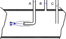
Now the static head of the fluid (p /ρg ), that is the
height that the fluid rises in the tube with the fluid velocity at zero, is
indicated by the tube at position B. At the interface of a flowing liquid with
a solid surface the fluid velocity is zero. The head at position A is a
measure of the stagnation head (p /ρg +u 2 /2g)
Reference ..Stagnation point.
Now if the flowing fluid was in an open stream that static pressure would be the
atmospheric pressure and the stagnation head would be simply the level of
fluid in the manometer above the surface level of the flowing fluid. For an enclosed stream the velocity head is the difference
in level of the static head as measured by tube B and the stagnation head as
indicated by Tube A. The level of fluid in the tube at C is not
useful because the fluid is flowing past the end of the tube.
The figure below shows a typical design of pitot tube flow meter. The
inner tube pressure is the stagnation pressure and the annulus surrounding
the inner tube is at the static pressure i.e. it indicates the pressure at the surface of the pitot tube which is static.
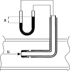
If ρ m is the density of the manometer fluid and ρ is the density of the flowing fluid then the the fluid velocity results from the equation.
u = C √ (2 Δp /ρ)........
Δp = (ρ m - ρ)gx....... and....
Δh = [(ρ m / ρ ) - 1] x
The pitot tube meter is used to indicate the velocity of the fluid flow in an enclosed pipe or duct.
It is very accurate and involves minimum energy losses in the flowing fluid. It requires good alignment with
the flow direction to achieve best results. Pitot tube meters are able to achieve
accuracy levels of better than 1% in velocity with alignment errors of up to 15o
Venturi Meter Reference ..Fluid Flow
A venturi meter includes a cylindrical length, a converging length with an included angle
of 20o or more, and short parallel throat, and a diverging section with an included angle of about 6o.
The internal finishes and proportions are such to enable the most accurate readings while ensuring minimum head losses.
Assuming an inviscid fluid with no losses due to viscocity. The velocities at section
1 and 2 are u 1 and u 2. The velocities are steady and uniform over areas A 1
and A 2
The contuity exquation applies therefore A 2 u 2 = A 2 u 2 = Q
Applying bernoulli's equation to a streamline passing along the axis between the two
sections( 1 & 2 ).
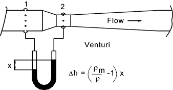
Applying bernoulli's equation to the two sections.

Therefore the ideal discharge is given by


Now in practice there is a slight friction loss between 1 and 2 which would result in
a high Δh reading and a consequent value of Q which is too high. For real fluids
therefore a factor is introduced called the coefficient of discharge factor (C d ).
For low viscosity
fluids C d = 0,98. The actual discharge as measured by a venturi is therefore given by.

Design and performance parameters of venturi flow meters are provided in BS EN ISO 5167-4:2003
Nozzle Flow Meter
The nozzle as shown is practically a venturi with the diverging part removed.
The basic equations used are the same as for the venturi meter. The friction losses are slightly
larger than for the venturi but this is offset by the lower cost of the unit. The fact that the manometer
connections cannot be located in the ideal positions for measuring the required piezometric pressures is allowed for in
selection of the coefficient of discharge factor C d..
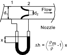
Design and performance parameters of nozzles flow meters are provided in BS EN ISO 5167-3:2003
Orifice Flow Meter
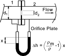
The simplest and cheapest method of measuring the flow using the bernoulli equation is the sharp edged
orifice as shown below.
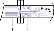
The fluid flow pattern in the region of and orifice is shown in the diagram below..
Application of Bernoulli's equation to the fluid flowing through the orifice.
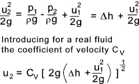
Now u 1 = Q /A 1 and u 2 = Q /A c where
A c = The area of the vena-contracta which is the reduced area of the fluid after leaving
the orifice hole. (A c = C c A 2 ).
A 2 = the area of the orifice
and C c is the Coefficient of contraction.
Finally C d = Coefficient of discharge = C c.C v
Using these factors a relationship for Q can be developed from the above equation

To arrive at a final equation a overall discharge coefficient C is introduced.

Now letting β = d 2 / d 1 that is β 2 = A 2 / A 1.
The equation for flow through an orifice becomes

Note: This equation is very similar to the equation provided in BS EN ISO 5167:2 except that
an expansion coefficient (ε )is introduced to cater for the measurement of compressible fluids. The equation provided
in the standards is .

Values of the discharge coefficient C are provided in BS EN ISO 5167:2 for the different meter tapping arrangements,
for different values of β against Reynold number ranges.
Small table showing C values for different Reynold numbers and β values . Detailed tables are provided
in BS EN ISO 5167:2
| β |
Re |
| 5 x 10³ |
1 x 10⁵ |
1 x 10⁸< |
| 0.25 |
0,6102 |
0,6025 |
0,6013 |
| 0.5 |
0,6284 |
0,6082 |
0,6036 |
| 0.75 |
0,6732 |
0,6171 |
0,6025 |
Flow Conditioning The accuracy of the flow
measuring devices is very much affected by uniformity of the approaching
fluid flow.
Therefore ideally there should be a straight length of piping before the
flow measuring
device. It is generally accepted that for accurate flow readings there should
be 50 pipe diameters of straight piping before the metering device following any
pipe bend, valve, tee, reducer etc. The relevant standard provides a
range of recommended minimum straight lengths
depending on the nearest upstream fittings varying from 5 to 44 lengths. This length can be reduced if flow
straighteners or flow conditioning devices systems are used upstream of the flow
measuring device. A flow straightener is designed to remove swirl from
the flowing fluid. A flow conditioner is a device which removes swirl
and also redistributes the velocity profile to produce near ideal metering conditions.
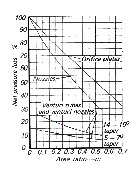
Losses resulting from flow metering devices
The orifice plate and, to a lesser extent the nozzle has significant kinetic
energy losses downstream of the metering device as the locally
generated kinetic energy is dissipated. The figure below illustrates the extent of these losses.
| 


