Hydraulics Index
Hydraulic Oil /Reservoir /Filters
|
Introduction Hydraulic Oil Properties Hydraulic Oil Types Reservoir Filters |
|
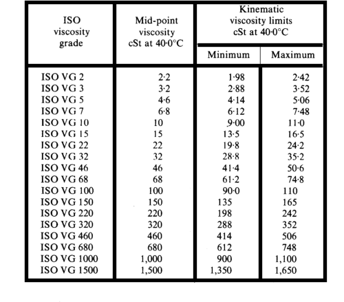
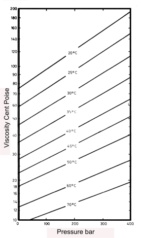
Introduction The earliest hydraulic systems were based on using water as the fluid medium. Water has the prime advantage of fire resistance and is sometimes still used today with additives to reduce corrosion effects. Hydraulic fluids based on castor oil and alcohol were also used as these are compatable with the natural rubber seals available at the time. The introduction of more exotic seal materials based on synthetic rubber enabled the introduction of mineral oils which are used today for the majority of hydraulic transmission systems. The exceptions being applications where fire resistance is of paramount importance. The notes below relate to hydraulic oil, the design of the oil tanks (reservoirs ) used to contain the oil in hydraulic power packs, and the filters used to remove small particles and contaminants from the circulating oil. Hydraulic Oil In hydraulic systems the fluid is of primary importance for transferring the energy of motion from the pump to the actuators. The hydraulic fluid characteristics are important in maintaining the equipment performance and operating life and it is important to use a clean high-quality fluid to ensure an efficient hydraulic system operation . A hydraulic fluid has four principal functions: Transmission of power: This is enabled by having a fluid with low compressibility and low resistance to flow. Fluid properties which are relevant to successful operations of hydraulic systems are listed below Lubrication Properties The principal advantage of using mineral based hydraulic oils is the enhanced lubrication properties of the fluid which reduces the friction between sliding surfaces. There are two recognised lubrication regimes : Hydrodynamic lubrication which occurs when a thick layer of lubricant is present between the surfaces and the fricton is directly related to the fluid viscosity: Boundary lubrication when a very thin layer of fluid lubrication is present. This occurs when the conditions are extreme and can result in contact at surface irregularities. Even under ideal operating condition with hydrodynamic lubrication there can be occasions e.g. at stopping and starting and transient overloading when boundary lubrication can occur. Viscosity Detailed information about Viscosity is found at my webpage. Viscosity . Thicker oils have higher viscosities and result in increased friction in the piping and hydraulic devices. Thinner oils of low viscosity cause increase leakage and increased wear of sliding parts. The modern method of grading the viscosity of hydraul oil is to use the ISO 3348 viscosity classification as shown below.
The reference temperature of 40 �C relates to the hydraulic system operating temperature. Each
Viscosity grade (VG) within the classification has approximately a 50% higher viscosity than the preceding one. The the minimum and
maximum values of each grade ranges �10% from the identified mid point. For example, ISO VG 32 refers to a
viscosity grade of 32 cSt � 10% at 40�C. The viscosity at another temperatures can be calculated
using the viscosity at 40�C and the viscosity index (VI), which represents the temperature dependency of the lubricant. The higher the VI the less the viscosity
changes with termperature. Special oils with VI of 125 to 150 have been developed with a very low dependency of
the viscosity on the temperature.
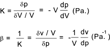
Chemical Stability Chemical stability is another property which is important in the selection of a hydraulic fluid. It is defined as the liquid�s ability to resist oxidation and deterioration over time. Modern industrial oils have been formulated to ensure that under arduous operating conditions the oil does not break down resulting in contamination of the fluid and reduction in the lubrication properties. Bulk Modulus /compressibility All hydraulic fluids are, to a small extent, compressible and this is generally expressed in terms of the bulk modulus which is the reciprocal of the compressibility and has the units of pressure. The bulk modulus K is basically [the change in pressure dp] / [the proportional change in volume (dv/V)]. The equation for the bulk modulus K and the compressibility β is shown below.
The Bulk modulus of is different when a sudden change in pressure occurs (isentropic) to when the change in pressure is slow (isothermal ). A typical isentropic value of bulk modulus, of an hydraulic oil, is K = 24.1 kBar, for an isothermal value of the same fluid under the same conditions a K = 18,8 kBar results. Fire resistance The only fire resistant hydraulic fluid is water which is now rarely used. However a range of mineral based hydraulic oils are available which have some degree of fire resistance in that they are difficult to ignite and resist the tendency to propogate flames. In most hydraulic systems there is virtually no fire risk and so this is not a problem. However there are high pressure systems in which a small leak can result in fine spray /mist escaping which can be easily ignited in an engineering environment. It is therefore vital that if a hydraulic system is used in a region with the risk of hot surfaces and / or sparks /flames then a fire resistant fluid is used. Heat transfer capability An hydraulic fluid should clearly have good thermal capacity and conductivity. The operation of the pump and motors and other hydraulic actuators are not 100% efficient and the losses result in heat being generated. This heat results in the temperature of the oil increasing . This hot oil is then cooled as it flows back to the reservoir and it is cooled within the reservoir. The hotter the oil the greater the heat transfer through the piping walls and the walls of the reservoir. Generally there is sufficient heat transfer capacity to remove the heat generated with the oil remaining at a suitable working temperature (Say 60-70 deg. C.). If there is not sufficient heat transfer capacity there is a need for a cooler in the fluid return circuit. Fluid Density The density of a typical mineral oil is about 0,9 kg/litre. (sg = about 0.9). Resistance to foaming /Air entrainment Foam is an emulsion of gas bubbles in the fluid. Foam in a hydraulic system results from compressed gases in the hydraulic fluid. A fluid under high pressure can contain a large volume of air bubbles. When this fluid is depressurized, as when it reaches the reservoir, the gas bubbles in the fluid expand and produce foam. Any amount of foaming may cause pump cavitation and produce poor system response and spongy control. Any tendency of an hydraulic fluid to foam, as is moves round the hydraulic circuit, or is agitated as it returns to the reservoir, or is drawn from the reservoir is a great problem. This could result in poor performance and failure of the pumps and a significant reduction in the performance of the hydraulic actuators Toxicity All hydraulic fluid has a limited life and has to be disposed. Maintenance/ installation/ decommissioning personnel all come in intimate contact with hydraulic fluid when undertaking their work. It is therefore necessary that there is no toxicity risk involved in the handling and disposal of hydraulic fluid. Cost and Availability In selecting a suitable hydraulic fluid, cost and availability, can be and important factor especially when it need to be regularly replaced or replenished, as on machinery/ vehicles used in agriculture, construction and heavy goods vehicles. For more critical applications requiring fire resistance and in precision electro-hydraulic servo systems the fluid cost/ availabiliy may not be of prime concern but is is one of the important factors which need to be taken into account Volitility Low volatility is desireable in hydraulic fluids . Volatility is the rate at which fluids vaporize. High volatility can lead
to fluid loss and potential equipment damage. Oil Types There are numerous types of fluid used in hydraulic systems. Currently, liquids used include mineral (petroleum based) oil, water, phosphate ester,
water-based ethylene glycol compounds, and silicone fluids. The three most common types of hydraulic liquids are
petroleum-based, synthetic fire-resistant, and water-based fire-resistant. The most common hydraulic fluids used in general/mobile systems are the petroleum-based oils. These fluids
contain additives to protect the fluid from oxidation (antioxidant), to protect system metals from corrosion (anticorrosion),
to reduce tendency of the fluid to foam (foam suppressant), and to improve viscosity. Petroleum-based fluids are
used in mobile systems, electrohydraulic servo systems general machinery systems, aircraft systems,
shock absorbers, brakes, control mechanisms, and other hydraulic systems using seal materials compatible with petroleum-based fluids. ............................. Phosphate ester fire-resistant fluid are often used when fire resistance is important. These fluids will burn if sufficient heat
and flame are applied, but they do not support combustion. The disadvantage of phosphate ester fluids are that they will
attack and loosen commonly used paints and adhesives, deteriorate many types of insulations , attack many gasket and seal materials.
............................. The most widely used water-based hydraulic fluids may be classified as water-glycol mixtures and water-synthetic base mixtures.
The water-glycol mixture contains additives to protect it from oxidation, corrosion, and biological growth and to enhance its load-carrying
capacity. Fire resistance of the water mixture fluids depends on the vaporization and smothering effect of steam
generated from the water. The water in water-based fluids is constantly being driven off while the system is operating.
Therefore, frequent checks to maintain the correct ratio of water are important. Water glycol based fluids contain 35-60% of water in form of solution (not emulsion) .
............................. Silicone synthetic fire-resistant fluids are frequently used for hydraulic systems which require fire resistance, but which have only marginal requirements for other chemical or physical properties common to hydraulic fluids. Silicone fluids do not have the detrimental characteristics of phosphate ester fluids. These fluid do not provide the corrosion protection and lubrication of phosphate ester fluids, but they are excellent for fire protection. Typical Hydraulic oilsBelow are tables showing properties of some typical ISO classified hydraulic oils
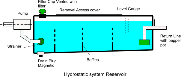
Oil Reservoir The design of the reservoir should be of sufficient capacity to contain all of the fluid in the hydraulic
system with at least a 10% excess margin. For static hydraulic transmission systems the reservoir
capacity of about 6 x the pump flow/minute should be available. On mobile units it is often necessary to have a smaller
reservoir. The construction of the reservoir is generally based on a simple rectangular box with a floor sloping down to a drain plug. The tank should have internal corners suitably designed to ensure convenient cleaning and the surfaces should be desecaled and painted with a paint which is corrosion resistant and suitable for the oil contained. The tank should include a sealed lid which includes a Filler/breather cap with air filter included and a sight level gauge on the side.
Filters Filters are an important part of hydraulic systems. Metal particles are continually produced by mechanical
components and need to be removed along with other contaminants. The current convention is to provide the following filters in a hydraulic system. 1)The reservoir will be sealed and provided with a filler cap with an air filter included to minimise contamination of the fluid from the environment. It is also good practice to circulate the oil continuosly for a period of time, with the components with very small
gaps being out of circuit.
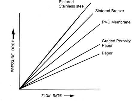
When the oil has been suitably cleaned the filters elements are replaced and the sensitive components are introduced into the circuit. There are many types of filter in use including felt, woven wire, impregnated paper. and sintered metal. Those which are capable of being easily cleaned are usually above 25 μm are used as suction filters. the most popular throw away filters are impregenated paper filters which are supplied in ranges < 2 to 40 μm.. these are used in suction returen and also high pressure filters. The allowable flow through a filter element depends on the permeability of the oil and the area of the exposed media to the oil flow. A crude measure of the permeability is shown on the graph below.
It is important to note that all hydraulic filters have to be regularly serviced . This generally involves replacement of the filter element. With some filter systems this may involve cleaning the element and replacing it. Of all maintenance tasks this is probably the most important. Some filter systems have warning instruments to identify that the filters are blocking. The frequency of replacement is clearly dependent on the duty. Table showing levels of filtration required in hydrualic systems
| |||||||||||||||||||||||||||||||||||||||||||||||||||||||||||||||||||||||||||||||||||||||||||||||||||||||||||||||||||||
Useful Links
|
|
Hydraulics Index
