Introduction
The object of all compressors is to raise the pressure of a gas with the minimum
expenditure of energy...
There are four principle types of air compressors
- Reciprocating compressors..Gas is compressed by positive displacement pistons in cylinders. Flow being controlled by valves.
- Turbomachinery .. Gas is driven by high speed impellers rotating in confined case
- Rotary Machines.. Gas is compressed by rotors provided with lobes, gears, vanes.. Near positive displacement
- Ejectors .. Gas is moved using kinetic energy induced by high velocity jet through nozzles
|
When considering turbo machinery a number of different designations are used
- Pumps - mainly for liquids
- Fans move gases against small pressure differences with little change in density
- Blowers- move gases with some slight pressure differences
- Compressors are used to move gases and provide significant pressure increases
|
Reciprocating compressors
Reciprocating compressors are often used with air reservoirs to provide compressed
air for industrial and civil duties driving air tools etc. Reservoirs have to
be used because reciprocating compressors provide a pulsating air delivery..
The figure below shows a hypothetical indicator diagram for a single stage -single acting
reciprocating compressor.
a ->1... Air is drawn into the cylinder on the suction stroke
1 ->2... The suction valve is closed and air is compressed according to the law Pvn = c
2 ->b... The delivery valve opens and air is delivered under pressure
b ->a... The delivery valve closes and the suction valve opens
|
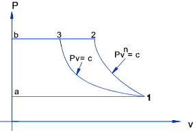
The cycles shown is assumed to follow a series of equilibrium states and the gas is
assumed to follow the equation of state . PV = RmT throughout....
The theoretical work done on the air per cycle is the area enclosed by [ a-1-2-b- a ] which equals
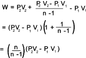
ref..Polytropic Process
If C is the rate at which the cycles are repeated then the rate at which energy is imparted to
the air =

The ideal compression requiring the minimum amount of work is the
perfect reversible isothermal compression process
which obeys Boyle's law PV = c. This is represented by 1-3. The work saved ber
cycle is [ 1-2-3-1 ]. If the compression was isothermal the work done per cycle would be [ a-1-3-b-a ] which
is
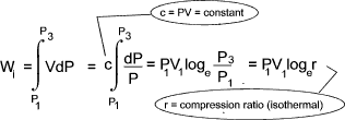
The compressor isothermal efficiency is a measure of the departure from the ideal compression process
and is defined as

Clearance Volume effect
A practical single stage compressor cylinder will have a small clearance
at the end of the stroke. This clearance will
have a significant effect on the work done per cycle.
In operation the air in the clearance volume expands to 5 before any fresh air is drawn
into the cylinder. The stroke is from 1 to 2 with a swept volume of (V2 - V1 ) but the suction
is only from 5 to 2 giving a volume of (V2 - V5 ) taken into the cylinder on each stroke.
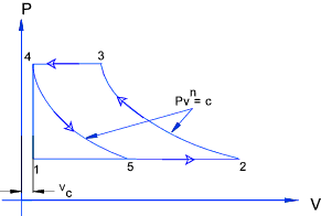
Effect of Clearance Volume
The volumetric efficiency obtained from the hypothetical indicator diagram is :

Assuming compression curve 2->3 and the expansion curve 4->5 follow the same law PVn = c then..

The volumetric ratio of compression (V2 /V 3 ) = the volumetric
ratio of expansion (V5 /V 4 ) = r v. The volumetric
efficiency =

That is

It is clear that the smaller the clearance volume Vc the larger the volumetric
efficiency will be. In practice is is possible to get the clearance volume
down to 3 to 5% of the stroke....
When clearance is taken into account the work done per cycle =

The hypothetical power of a single stage compressor (kW working on c cycles /s)

The actual compressor diagrams differ from hypothetical diagrams because
of valve opening and closing
delays and component inertia. A typical actual indicator diagram is shown below.
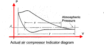
A good approximation of the volumetric efficiency is indicated by the ratio of x to y measured at
the atmospheric pressure line..
The actual performance of a reciprocating compressor used as pump is measured by the
ratio.

Multi-stage
When air at high pressure is required, multi-staged compression is more efficient
than using a single stage compressor. Also single stage compressors delivering
high pressures result in high gas temperatures which effect the lubrication and increase the
risk of burning.
It is required to compress air from P1 to P4. The diagram below shows
the curve for single stage compression .a-b-c-k-h. The curve for ideal isothermal compression
is also shown a-b-j-h.
The area enclosed by the curves indicates the work done per cycle and it is clear that
the work done in the ideal isothermal process is far less than that done in the single stage compression.
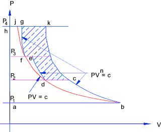
Assume a three stage compressor process is used.
The air is compressed from P1 to P 2 (a -> c)
and the air is transferred into a receiver and cooled to its original temperature (c -> d) and the air is then transferred
from the receiver to a second cylinder and compressed to P3 (d -> e) .
The air is then transferred to a second
receiver and cooled back to its original temperature (e -> f) and transferred again to a third cylinder and compressed to
P4 (f -> g).
The overall process is represented by curve a-b-c-d-e-f-g-h.
The cooling brings the process closer toward the ideal isothermal (constant temperature) curve. The
saving in work done per cycle is identified by the shaded area.
Rotary and Turbo Compressors
Rotary or turbo-compressors deal with larger flow rates of air than reciprocating compressors but
usually at lower delivery pressures. Rotary compressors can be driven by high speed electric motors, steam
turbines, and internal combustion engines. They are usually multi-stage machines of the centrifugal
or axial-flow types.
In centrifugal compressors a number of impellers are mounted on a a common rotor in a robust casing. Air from
the atmosphere enters the eye of the first impeller it then acquires kinetic energy from the rotating
impellers. The air is directed from the periphery of the impeller into a
stationary diffuser vanes which are designed to convert the kinetic energy of the gas to
increased pressure.
The gas is directed inwards to the eye of the next impeller and the process is repeated as it passes through
each stage the pressure being progressively increased.
In the axial-flow compressor, the air is compressed while continuing its original
direction of flow . The rotor has fixed blades that force the air rearward
much like an aircraft propeller. In front of the first rotor stage
are the inlet guide vanes . These vanes direct the intake air toward the
first set of rotor blades. Directly behind each rotor stage
is a stator. The stator directs the air rearward to the next rotor stage
Each consecutive pair of rotor and stator blades constitutes a pressure stage.
Higher duty rotary compressors are usually provided with water cooling with
intercoolers.
The volumetric efficiency of turbo-compressors is usually defined by the ratio.

Although minimum work input is usually achieved with a constant temperature (isothermal)
reversible process, compression in rotary compressors is most often assessed relative
to the reversible adiabatic process ( isentropic -constant s processes). The pv diagram below
shows the different processes.
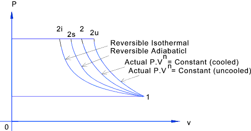
An ideal compression process with no losses would be adiabatic and real processes are compared to this
by having using the adiabatic- isentropic efficiency which is defined as.

The power for reversible adiabatic compression is calculated from.

c = cycles traced per unit time and m = mass of air pumped per unit time. As cp = γ R /(γ-1)
and cp (T2s- T1 ) = (h2s - h1 ) the above expression can be rewritten

The isentropic efficiency of a rotary compressor based on the hypothetical indicator diagram is calculated by

The isentropic efficiency of a uncooled rotary compressor when all the energy is used in increasing the enthalpy
of the fluid can be expressed as

Motors
There are many kinds of air motors used for powering tools and mechanisms which use compressed
air. These are specially designed units which are very compact and are able to operate
at high speeds with built in torque limitation.
Typical designs of air motors include rotary vane, axial piston, radial piston,
gerotor, turbine, V-type, and diaphragm. Rotary vane, axial- and radial-piston,
and gerotor air motors are most commonly used for industrial applications.
These designs operate with highest efficiency and longevity when using lubricated air.
Unlike steam air cannot, conveniently, be used expansively because the resulting cooling effect
would result in freezing of the moisture being carried in the air. If the moisture in the
air is removed then the air can be used more flexibly.
The efficiencies of air motors based on non-expansion cycles is about 20%. With the efficiencies
or compressors being about 60% then pneumatic drive systems have efficiencies of less than 12%.
This compares unfavorable with internal combustion electric motor drive systems.
The primary advantages justifying the use of pneumatic drive systems are
- Safety - air motors can safely be used in locations with explosive risk resulting from ignition sources due to electrical devices
- Convenience - air motors are generally very compact and include built in overload protection
- Capital Costs - air motors are often very low cost units
- Maintenance/Operation - air motors cost little in maintenance and can be easily operated by semi-skilled operatives
- Installation - most industrial sites have compressed air systems installed.
|
..... Notes to be added...
|


