|
|
|
Welding
|
Introduction A weld occurs when pieces of metal are joined by causing the interface to melt
and blend prior to solidifying as a uniform metal joint. This process
may be caused by heat, pressure or a combination of both. When heat alone is used
the process is called fusion welding.
Calculation relating to welded joints can be found on webpage... Weld Stress Calculations Soldering Soldering is applicable for low duty joining of sheets, tubes, electrical and electronic connections.
It is an understated but widely used process through engineering , construction, electrical and electronic industries.
The solder is an alloy of lead-tin which melts at a temperature of 180 - 280o depending on the composition
The surfaces to be soldered are cleaned and prepared with a flux. The area to be joined is preheated
and the solder when applied wets the metal and produces an intermettalic bond.
If the gap to be filled is controlled to about 0,1mm then the solder is drawn into the joint by capilliary
action to produce a uniformly filled joint. The joint is heated using a soldering iron , gas flame ,
or by use of bath of liquid solder. It is important the surfaces are suitably located when the joint
is being made and there are no separating forces. The flux is needed to remove oxide films on the unjoined metal, and to protect the surfaces from oxidisation , and to reduce the surface tension of the filler to assist in penetration. For soft soldering the flux is generally zinc chloride or resin. Brazing Brazing is a mechanical joining process which is similar to soldering but uses fillers having a
significantly higher melting points ( 450 to 800o ). Copper, nickel and silver and the most frequently-used base metals for brazing alloys. The process is used widely for
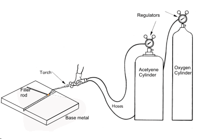
machanical joining and sealing for higher preformance applications on copper based alloys e.g. piping and heat exchangers and vessels. Gas Welding and Flame cutting In gas welding, the heat to produce fusion of the parent metal and
filler rod is provided by burning a suitable gas in oxygen or air. A number of gases can be
used but acetylene is the most popular, since it burns in oxygen and gives a high flame
temperature of 3100o - 3200o. C. . Oxygen and acetylene stored in
cylinders under pressure are passed through flexible tubes
to the torch, which is either hand-operated or mechanically manipulated.
By adjusting the proportions of oxygen or acetylene the flame can be neutral, or have either
reducing or oxidising properties. For most materials a neutral flame is used but,
for welding high carbon steel , or aluminium and its alloys an
oxidising flame is used as, by these means, the volitilisation of the zinc is supressed.
The gas pressures at the torch are each regulated to be about 7 to 70 kPa.
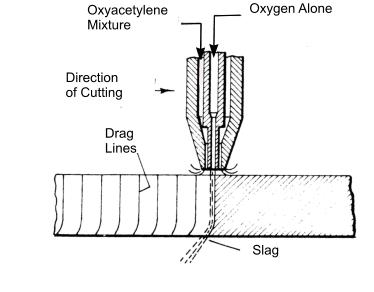
Flame Cutting Flame cutting using an oxyacetylene flame is a well-known engineering process.
The cutting torch may be manually operated if low accuracy is permissible, or if higher accuracies are required,
the torch is mechanically mounted and controlled numerically ,or by using a tracer system.
An outer oxyacetylene gas flame is used to preheat the metal to about 1000oC . An inner by a jet of
oxygen is then rapidly initiated which oxidises the red-hot metal, enablng thick sectons to be cut.
The cutting process is then progressed with both jets on.
Manual Metal Arc Welding Process Electric Arc welding is based on providing an electric circuit comprising the Electric current source the feed and return path, the electrode and the workpiece. The arc welding process involves the creation of a suitable small gap between the electrode and the workpiece. When the circuit is made a large current flows and an arc is formed between the electrode and the workpiece. The resulting high temperatures causing the workpiece and the electrode to melt The electrode is consumable. It includes metal for the weld, a coating which burns off to form gases which shield the weld from the air and flux which combines with the nitrides and oxide generated at the weld. When the weld solidifies a crust is formed from the impurities created in the weld process (Slag). This is easily chipped away. MIG & TIG WeldingThe Metal Inert Gas Process uses a consumable electrode of wire form and an inert gas shield of
carbon dioxide when welding carbon steel.. The wire electrode provides a continuous feed
of filler metal allowing welds of any length without stopping. The inert gas shield eliminates
slag and allows cleaner and stronger weld.. This process is used widely for automated welding
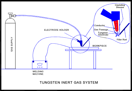
using robots. The Tungsten Inert gas (TIG) system uses a non-consumable electrode of tungsten
and also provides an inert gas shield of argon or helium.
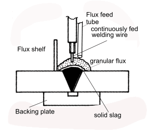
This process involves the welding arc being continuously submerged under a mound of
granular flux. The bare metal is fed automatically at a rate which maintains the welding arc.
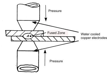
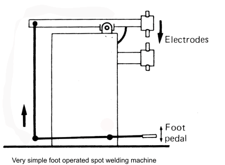
Resistance Welding Spot Welding Electric spot welding in the main form of resistance welding. In spot welding, high current at a low voltage passes through a spot on two pieces of metal, usually sheet metal, for a short period of time. This process is done using a spot welder. Resistance to the current flow results in localised heat generation which melts the metal between the spot weld electrodes. The electrodes /welding tongs exert a moderate pressure forcing the two metal pieces together at the spot . The weld results at the interface. The actual spot weld operation includes the following SQUEEZE TIME - Time between pressure
application and weld. The welding time can vary from 1 to 120 Hz . Assuming a 50 Hz supply in the UK e.g 25 Hz = 0,5 seconds The tip dia can vary from 2.5mm to 15mm dia based on the combined sheet thickness being welded. A rough formula for mild steel sheet = Dia of tip (mm) = 2,5mm + 2. Sheet thicknes(mm)
Typical specification range
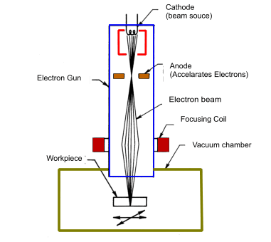
Arm length.. 300mm to 450mm Projection Welding Projection welding is similar to spot welding except that one on the surfaces in contact with the electrodes as a local projection. The projection defines the area of weld and not the size of the electrodes. The projection is normally on the thicker component or on the component having the highest reistance. The process generally results in the collapse on the projection when the weld is formed. .Seam Welding Seam welding is a variant of the spot welding process in which the current is fed continuously or intermittenly to two thin copper alloy wheel electrodes which replace the rod electodes used for spot welding. This process is ideal for producing fluid tight joints in cans. .Solid State Welding Solid state welding is a term used for welding processes which produces joining at temperatures essentially below the melting point of the base materials, without the need for brazing filler metal. Pressure is generally required but not always. These welding processes include cold pressure welding, diffusion welding, explosion welding, forge welding, friction welding, hot pressure welding, roll welding, and ultrasonic welding. Electron Beam Welding In this process a concentraed beam of electrons bombards the base metal, causing it to melt
and fuse. The process is most efficient wehn done in a vacuum.
Therefore the size of the vacuum chamber limits the size of the workpieces that can be welded.
Advantages include the ability to produce welds of extremely high purity, ability to melt any known
material , ability to weld dissimilar metals and tbe ability to make welds with depths as great as 150mm.
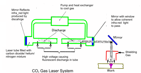
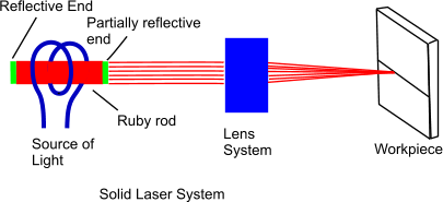
Laser Welding.. (Light Amplification by Stimulated Emmission of Radiation). The laser beam is a concentrated beam of light with sufficient energy to generate the heat at the base metal surface
to cause fusion. There are two types of lasers in use (1) gas lasers and 2) solid lasers.
Gas lasers provide a continuous laser beam that is best suited to continuous welding and cutting . Solid lasers release their energy
in short bursts or puses at a rate of 6 to 10 per minute . As each pulse only lasts for a few millionths
of a second the base metal is liquid for only moments and there is limited time for chemical reactions to occur. Therefore flux type protection is not
required to obtain sound welds.
Welding process Designations The welding process designations provided below are based on BS EN ISO 4063 and are used when identifying welds to BS EN 22553
| ||||||||||||||||||||||||||||||||||
Links Providing information on Welding
|
|
Manufacturing Index
