Introduction
To determine the performance of a bolted joint it is necessary to calculate
the joint stiffness. That is the deflection of the joint under a bolt loading condition
When geometry of the bolted joint is an annulus with an OD less than 2,5 x the bolt diameter the joint
stiffness can be conveniently calculated using k = EA/l . When the joint includes a non-metallic gasket
or material with a low modulus of elasticity then this item may have such a low stiffness value that the stiffness
of the metal parts of the connection will have very low impact on the overall stiffness.
It is very difficult to obtain theoretical values of joint stiffness because a
number of factors affect the result including.
- The effect of the angle of the screw thread
- Screw hole size
- Surface finish of contacting faces
- Flatness of contacting faces
- Use of Washer
- Selected size of contacting surface (d and D)
- Condition of surfaces between clamped plates
|
Any of these factors can have a significant effect on the resulting joint stiffness
The notes below identify methods which approximate the loading regime
which has been found to occur by various studies using different methods.
Overall stiffness evaluation for multi-component joints
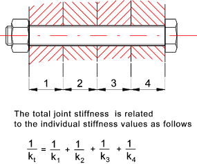
A bolted joint can include a number of separate parts. The relationship
between the individual stiffness values of the parts and the total stiffness of the clamped
joint is as shown below..

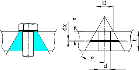
The sketch below shows a bolted surface. It has been shown using using
ultrasonics and FEA that the pressure in a bolted surface is greatest under the bolt
head and reduces as the distance from the bolt interface increases. A method of
be approximating the force distribution is based on use of the cone geometry as
shown. Various cone half-apex angles are used but for systems using a
washer-face annulus and with hardened steel, cast iron or aluminium an angle of
25o to 35o considered reasonable.
These notes relate to half apex angle of 30o

Referring to the contraction of a small element dx of cone subject to a load P as shown.

The area is determined as follows

Substituting this into the equation for contraction of an element..

To obtain the total deflection the equation above is integrated between 0 and t.

Using integration manipulation techniques this results in

The spring rate of the truncated cone is therefore ..

The bolt hole diameter is d, the diameter of the applied pressure e.g.the washer
diameter, is and the plate thickness is t.
For a half apex angle of 30o which provides a reasonable value
for many engineering metals, the equation simplifies to..

Important Note:
Widely different stiffness values result from different studies. It has also
been proved that different loading conditions and surface conditions also affect
the resulting stiffness.
The variation in half apex angle α can be notice from the different
studies completed. Differences result from various reason including
D/d ratios differences and surface finish difference
| Originator | Technique | Surface Type | α |
| Link 3 below | Ultrasonics | Ground | 41o |
| Link 3 below | Ultrasonics | Turned /Ground | 68o |
| Shigley and Mischke | Analysis | Any | 30o |
| Ito | Ultrasonics | Ground | 70o |
| Gould and Mikic | Analysis | Smooth | 38o |
Table A
Showing stiffness values for steel plate E = 207 kN/mm2 and a half apex
angle α of 30 o calculated using equation X above..
d= bolt dia and D = 1,5 d = approximately as would result from a
typical bolt or cap screw .
| - |
|
Plate Thickness (mm) |
| |
|
6 |
12 |
20 |
40 |
50 |
60 |
80 |
100 |
| d |
D |
k = Stiffness (MN/mm ) based on...E = 207 kN/mm2 and α = 30o |
| 6 |
9 |
2.757 |
2.102 |
1.83 |
1.619 |
1.576 |
1.547 |
1.511 |
1.489 |
| 8 |
12 |
4.245 |
3.098 |
2.622 |
2.254 |
2.178 |
2.127 |
2.063 |
2.024 |
| 10 |
15 |
6.009 |
4.236 |
3.503 |
2.934 |
2.817 |
2.739 |
2.639 |
2.579 |
| 12 |
18 |
8.047 |
5.514 |
4.47 |
3.66 |
3.493 |
3.381 |
3.239 |
3.153 |
| 16 |
24 |
12.945 |
8.49 |
6.661 |
5.245 |
4.953 |
4.757 |
4.508 |
4.356 |
| 20 |
30 |
18.932 |
12.017 |
9.191 |
7.006 |
6.556 |
6.253 |
5.868 |
5.634 |
| 24 |
36 |
26.008 |
16.095 |
12.055 |
8.94 |
8.3 |
7.867 |
7.32 |
6.986 |
| 30 |
45 |
38.658 |
23.236 |
16.974 |
12.163 |
11.175 |
10.509 |
9.664 |
9.149 |
| 36 |
54 |
53.75 |
31.605 |
22.638 |
15.768 |
14.36 |
13.41 |
12.207 |
11.474 |
Table B
Showing stiffness values for steel plate E = 207 kN/mm2 and a half apex
angle α of 60 o calculated using Equation X above. This table is provided
to identify the variation is stiffness using two different, but still relevant, values of α
d= bolt dia and D = 1,5 d = approx as would result from a
typical bolt or cap screw .
| - |
|
Plate Thickness (mm) |
| |
|
6 |
12 |
20 |
40 |
50 |
60 |
80 |
100 |
| d |
D |
k = Stiffness (MN/mm ) based on...E = 207 kN/mm2 and α = 60o |
| 6 |
9 |
5.627 |
4.929 |
4.642 |
4.423 |
4.378 |
4.349 |
4.312 |
4.289 |
| 8 |
12 |
8.108 |
6.886 |
6.382 |
5.995 |
5.917 |
5.864 |
5.798 |
5.759 |
| 10 |
15 |
10.88 |
8.996 |
8.216 |
7.616 |
7.494 |
7.412 |
7.31 |
7.248 |
| 12 |
18 |
13.939 |
11.255 |
10.142 |
9.284 |
9.11 |
8.993 |
8.845 |
8.757 |
| 16 |
24 |
20.909 |
16.216 |
14.27 |
12.764 |
12.456 |
12.25 |
11.99 |
11.833 |
| 20 |
30 |
29 |
21.76 |
18.758 |
16.431 |
15.955 |
15.635 |
15.231 |
14.988 |
| 24 |
36 |
38.203 |
27.878 |
23.602 |
20.284 |
19.604 |
19.146 |
18.569 |
18.219 |
| 30 |
45 |
54.079 |
38.121 |
31.526 |
26.407 |
25.355 |
24.647 |
23.753 |
23.211 |
| 36 |
54 |
72.426 |
49.629 |
40.231 |
32.938 |
31.437 |
30.426 |
29.148 |
28.373 |
Bolted joint comprising two equal plates
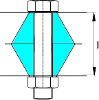
The force distribution on a typical bolted joint comprising two plates is shown below:

It is necessary to obtain a value for the stiffness for each part of the joint. In the case
above for each of the two plates.
If the plates are of the same material and similar thickness then the overall stiffness of the joint
is..

FEA work has been completed (Wileman ,Choudury & Green)for similar 2 part bolted joint with typical
washers (Dw = 1,5d) and joint members of the same material and an approximate
curve fit curve for the resulting relationship has been derived..

Values for A and B are provided in the following table...
| |
Poisson Ratio |
Youngs Modulus |
A |
B |
| Material |
|
GPa |
|
|
| Steel |
0,291 |
207 |
0,78715 |
0,62873 |
| Aluminium |
0,334 |
71 |
0,79670 |
0,63816 |
| Copper |
0,326 |
119 |
0,79568 |
0,63553 |
| Gray Cast Iron |
0,211 |
100 |
0,77871 |
0,61616 |
| General Case |
|
|
0,78952 |
0,62914 |
Example comparing stiffness value using two methods.
Consider two plates 20mm thick clamped with a 10m bolt using the table with a half apex
angle α of 30 o
k for each plate from Table A above = 3 503 kN/mm .... 1/ k t = 1/k + 1/k .
Therefore k t = k/2 = 1 7513 kN/mm.
Using the formula above with A = 0,78715,B = 0,62873,d = 10, l=40 and E = 207 OOO
k t = E.d.A exp (Bd/l)
= 1 906 kN/mm
| 


