Introduction
Calculating bolt loads is complicated if done correctly. The notes below
are very limited and are reasonable for none critical applications. There
is much specialist information in this field as identified in the links on this page and on the
screw index page. These notes do not include for fatigue loading, determination
of stiffness of joint, joint settlement, load application factors.etc etc.
It should also be noted that the bolt torque required, to achieve the same bolt stress levels, increases greatly
as the bolt size increases (torque = c. d 3). Therefore for larger bolts
very high torques are required and used of specialist bolt tensioning systems such as the "Superbolt multi-jackbolt" option should be considered.
Nomenclature
- A z = Area of plate - taking load ( m2)
- A b = Bolt Cross Section = Bolt thread root Area (m 2)
- D b = Bolt thread root diameter (m)
- d = Bolt nominal diameter (m)
- F e = External Load (N)
- F t = Thermal Load (N)
- F p = Preload Load (N)
- F = Total Load On Bolt (N)
- E z = Youngs Modulus of item z ( N / m2)
- L = Length of Bolt joint (m)
- L b = Length of Bolt (m)
- L j = Length of joint (m)
- k z = Stiffness of component z (N/m)
- k b = Stiffness of bolt (N/m)
- k j = Stiffness of joint (N/m)
- t z = Thickness of plate z (m)
- T = Bolt Tightening Torque (N.m)
- x z = deflection of item z /unit load (m/N)
- x b = deflection of bolt /unit load (m/N)
- α z= Coefficient of thermal expansion of component z (m/m/Deg.C)
- δ = deflection (m)
|
Bolt Loading Notes
It is accepted that a bolt preloaded to a fixed value is safer than a bolt
simply tightened to an arbitrary value. A preload of about 80% of the proof strength
of the bolt material is normally used.
Assume a bolt is used to clamp a joint to a set preload value and the bolt has a
low stiffness and the joint has a very high stiffness. An external
load is applied to tend separate the joint. Part of this load will cause
the further extension of the bolt (increase in bolt load). Part of the load
will result in a reduction of the compressive load on the joint.
e.g. If a high preload has resulted from a stretching of the bolt of 1mm and a compression
of the joint by only 0.001mm then an external load sufficient to achieve
joint separation will only increase on loading of the bolt by about 0,001mm/1mm (0,1%) x preload .
That is, if the joint is subject to a fluctuating load of 50% of the seperating force, The bolt will expererience
a negligible (0,05%) variation in tension. The bolt tension will be near constant.
It is noted that using longer small diameter bolts to clamp surfaces
results in relatively uniform bolt loading under varying external forces with reduced
risk of fatigue loading.

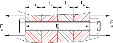
Assuming the assembly is bolted with a bolt preload of Fp and an external load
F eis applied..
Joint separation will occur when Fe = F (total load on the bolt) ..
i.e when no load is being taken by the joint
For an infinitely stiff bolt, separation will never occur as all of the external load will be
applied directly to the bolt with no resulting extension..
For a infinitely stiff joint separation will take place when the external load exceeds
the preload.
On application of an external force Fe. Some of the force will used to increase
the preload on the bolt and some will be used to reduce the loading on the
joint . The bolt loading diagram below shows the loading regime on the bolt
and joint
Bolted Joint diagram

The determination of the proportion of the load taken by the bolt
and by the joint is calculated using the component stiffness values.
The stiffness
is effectively the same as the Spring Rate ..
Stiffness = k = F / δ
Stiffness Considerations
Bolt stiffness
The relationship E = stress /strain = σ /e is used to determine the stiffness of
a bolt.
Stress = Force (F) /Area (A) and strain = Deflection (δ) / Length (L)
E = (F/A) /(δ/L) Therefore δ = FL/EA .

If the bolt length clamping the joint includes a number of different sections then the resulting stiffness is
determined using the relationship .

To allow for a certain degree of elasticity of the bolt head and nut a correction factor is
often used modify the length used in the stiffness calculations as shown below..

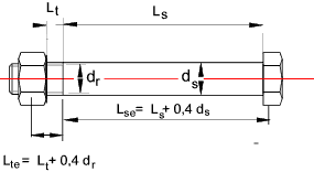
The stiffness of the bolt results from the stiffness of the bolt shank (dia ds )
and the stiffness of the bolt thread
(root dia dr ).
The length used to calculate the shank stiffness = L se = L s + 0,4d s
The length used for the threaded length section = = L te = L t + 0,4d r
Joint Stiffness
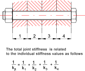
Note: It is very difficult to calculated the stiffness of a joint e.g one based on holes
drilled in a plate. A rough approximation can be made by assuming joint is an
annulus with and OD of 2,5 times the bolt dia and an ID = bolt diameter.
Additional notes on evaluating the joint stiffness are provided on
page Joint Stiffness
The mitcalc software (links below) is useful for obtaining a stiffness value of a joint.
The relationship E = stress /strain = σ /e is used to determine the stiffness of
a section .


Calculation of Load Distribution using Bolt/Joint Stiffness
A joint preloaded with a force Fp is then subject to an additional
load Fe which tends to separate the joint. The resulting deflection of the joint
and bolt are the same providing that Fe is less than the separation force.

It follows that

Following application of the external force the resulting total force on the bolt =

and the total force on the joint =

Thermal Loading
If all of the materials of the joint and the bolt are the same then any changes in temperature
will have negligible effect of the joint loadings. However if the joint materials
have coefficients of thermal expansion different to the bolt material changes in the joint loading
result from changes in temperature...
Let ..
Coefficient of thermal expansion of joint material = α j
Coefficient of thermal expansion of bolt = α b
Change of temperature = ΔT = T2- T1
Note: If there is a temperature fall then clearly T1 would be greater that T2 and ΔT would be negative
Length of joint = Length of Bolt ( L j = L b = L )
The expansion of the joint = ΔL j= α j ΔT.L
The expansion of the bolt = ΔL b= α b ΔT.L
The overall stiffness of the joint is calculated as follows.

The resulting change in the joint load is calculated as follows..

The total bolt load following temperature change is thus..

Initial Tension in Bolt
The initial tension in a bolt is crudely estimated for a bolt tightened by hand
by an experienced mechanic as follows. The tension resulting from this
equation would be reasonable safe for M8- 8,8 grade bolts and above.
Fp = K*d
- d = nominal diameter of bolt (m)
- Fp = Preload (N)
- K = Coefficient vary from. 1.75 x 10 6 N/m to 2.8 x 10 6 N /m
|
For a bolt tightened with a torque wrench the torque required to provide an initial
bolt tension may be approximated by the formula..
T = Fp * K * d
Typical K factors
| Steel Thread Condition | K |
| as received, stainless on mild or alloy | 0,30 |
| as received, mild or alloy on same | 0,20 |
| cadmium plated | 0,16 |
| molybdenum-disulphide grease | 0.14 |
| PTFE lubrication | 0.12 |
A more accurate value can be determined using the formula

Note: Relevant formulea for calculating Power thread torques and efficiencies are derived on webpage Power Screw Equations
- F p = Desired bolt Preload (N)
- p = Thread pitch (m)
- d m = Mean diameter of thread (m)
- μ = Coefficient of Thread friction
- μ c = Coefficient of collar friction
- α is the thread
angle / 2 (α = 30 o for standard metric threads & α = 29 o/2 for acme threads).
- r c = Collar friction radius (m)
|
Note: Friction values are found on this site on the coefficient of friction page..Coefficient of Friction
It can be proved that the majority of the torque is required to overcome
the thread and collar friction forces (approx ). Therefore any error in
the value of the friction coefficient will have a large variation on the bolt tensile
load. The above formula is in essence not a lot more accurate than the approximate
formulae above.
Note:
A very simplified version of this formula can be derive by assuming
μc = μ , d m = 0.92 d , α = 30o.
rc = 0.625 d.
If the denominator is simplified to π.dm
The equation reduces to T = Fp (0,159.p + 1,156. μ.d )
This provides a very crude relationship between the torque and the resulting bolt tension for a standard hex screw with no washer..
For important bolting applications it is recommended that the bolt preload is
is determined using direct bolt tension measuring techniques - see notes below.
Shear Stress In Bolts
In tightening a bolt stress is induced as a result of the bolt tension and bolt
torque.. The combined resulting shear stress is calculated as follows

- F Bolt Tension (N)
- Tf = Thread torque(N.m)
- A r = Thread Root Area (m 2)
- d r = Thread Root diameter
|
This formula is relatively conservative. For less conservative designs
A r can be replaced by A t as defined on page Thread calcs
and d r can be replaced by d t = Sqrt( 4.A t/π )
In general for static loading, the maximum shear stress in a bolt should not exceed about 75%
of the shear yield stress of the material. For variable loading the bolt should be designed
for endurance stress levels. Bolts subject to dynamic loading often lose their
initial torsion stress because the nut/bolt head tends to slip back if the collar friction
is not sufficient.
Methods of setting bolt preload /tension
High strength friction grip bolts and nuts require to be tensioned in
accordance with BS 4604 which specifies min. loads to be achieved (see Table 1).
It also specifies three methods of determining bolt tension, i.e.:
i) Torque Control
ii) Part Turn of Nut
iii) Direct Tension Measurement
Torque Wrench
This method is sometimes known erroneously as "torque control".
The bolts are tensioned in a tension calibrator on the site.
The wrench is then set to cut out at that torque (the wrench becomes "calibrated"),
and then all similar bolts that day are installed to that torque after the joint
is snugged first. Rotation during the tightening process must be limited
to a specific value. Actual results of tension in bolts produced by this method are acknowledged to
be highly variable, even when this method is followed exactly.
Turn Of Nut
After snugging the joint, the bolt shank and nut is marked and then a specific
amount of rotation is induced between the nut and the bolt.
The amount of rotation differs for different bolt lengths and diameters
and therefore must be known and understood by the bolt installers in advance.
The success of the method is dependent on a correct snugging of the joint, and
is dependent on the bolt head being held from turning so the bolt does not spin
in the hole.
Note: Turn-of-nut does not work correctly when the steel surfaces are coated
with a compressible coating such as high paint thickness or hot dipped galvanized zinc.
Direct Tension Indicator Washers
A number of direct tension indicator systems are available (see links below) the most popular being
the DTI washers.
..The notes below relate to DTI washers..
DTI washers measure the bolt tension developed during tightening, regardless of the
torque resistance of the bolt. By far the simplest method, a DTI washer
is put on the head or nut end of the bolt. The bolts are then slightly tensioned
snugging the joint by partially (but not fully) compressing the DTI (tightening the nut).
Then
all the bolts are tightened such that the DTI's are "crushed" to the point
where a feeler gage cannot be inserted half way around (tightening the nut). DTI's are
completely independent of the torque resistance of the bolt
assembly.
If the DTI is put on the nut end of the bolt, tightening can be done by one person
because it is not necessary access the bolt head side.
Other methods of setting Bolt tension
There are a number of more exotic methods of pre-setting the bolt tension including
- Using Strain gauges..Accurate /complicated /expensive. Some skill required
- Using ultrasonics instruments..Accurate and not expensive over the long term. Some skill required
- Using special bolts with built-in (mechanical or electronic) extension measurement e.g Rotobolt. Good but relatively expensive
- Using hydraulics (or heat) to pretension bolts See note below
- Using multi-jackbolt system (Superbolt) a variation of torque control.
|
Note:
Using heat is based on heating the bolt(and nut) to a set temperature.
The bolt is inserted quickly and the nut tightened snugly. The bolt is then allowed to cool
and the contraction results in the required tension.
If a tension Fp is required for a bolt with a CSA of Ab then
the required bolt stress is calculated σ= F p / Ab
The bolt is heated to a temperature of
T = [σ /(E.e)] + T o
E= Youngs Modulus (N/m2 )....e = Coefficient of thermal expansion
(m/m)/deg.C....To = ambient temperature (deg. C)
This method is very difficult to implement the bolt has to be heated while the bolted
joint has to be kept at ambient temperature. The accuracy of the heating method is very much
limited by quality of the procedure followed.
Hydraulic bolt tensioners use an annular hydraulic jack placed around the screw,
stretching it axially.
When the required stress level is reached, the nut is tightened snugly and then
the pressure released, resulting in a preloaded bolt without any frictional
or torsional stresses.
The hydraulic method can provide very accurate preload (+/- 1%) on long bolts
but it is less accurate on short bolts.
Preload Setting Error
| Operator "Feel" |
+/- 35% |
| Torque Wrench |
+/- 25% |
| Angle Torquing (Turn of nut) |
+/- 15% |
| Load Indicating Washer |
+/- 10% |
| Measuring Bolt elongation |
+/- 5% |
| Hydraulic Bolt pretension |
+/- (1% to 10%) |
| Strain Gauges / Ultrasonics |
+/- 1% |
| Superbolt multi-jackbolt tensioners |
+/- 5% |
| 


