Introduction
This page includes some notes on reinforced concrete as used in the construction of walls
and structures. It is important to note that I have based most of the content of this page on BS 8110 -1:1997.
This standard has now been replaced by Eurocode BS EN1992. There are a number of differences between BS 8110 and BS EN 1992 e.g
the symbols are generally different (N in BS8110 = N ED in BS EN 1992). The notes are not intended to enable detail design to the
latest codes they are simply provided to enable mechanical engineers to understand the topic and produce basic design studies. Formal
design work
must be completed in accordance with the relevant codes.
Reinforced concrete is probably the most prolific and versatile construction material . It is composed of two distinct materials
concrete and reinforcement , each of which can be varied in quality disposition and quantity to fulfill a wide range of construction
requirements.
The concrete composition is an based on three constituents : aggregate, cement and water.
These are mixed together in a homogeneous mass and are then put in place and left for the chemical and
physical changes to occur that result in a hard and durable material.
Information on concrete forms is provided on webpage concrete.
The strength and durability of the resulting concrete depends on the quality and quantity of each of the constituents and on
any additional additives have been added to the wet mix. Much of the mixing is now done off site by ready mix companies
..The strength of the resulting mixes is generally confirmed by a cube crushing test.
The concrete reinforcement is generally steel although other materials are sometimes used
such as glass fibre.
The main reinforcement bars are generally high yield deformed bars ( f y >= 460 N/m2 ) .
Reinforcement links are often mild steel ( f y >= 250 N/m2 ) although high yield steel is becoming more popular.
For reinforced concrete slabs and walls it is convention to use mesh reinforcement.
The reinforcement is generally located to compensate for the concrete being weak in tension e.g in
spanning beams the reinforcement is primarily located in the bottom half of a section and at the midspan. In a cantilever beam the reinforcement
will generally be at the top of the beam with the maximum concentration at the support.
In the notes below the characteristic strength for concrete ( f cu ) is the value of the cube
strength and the characteristic strength for the reinforcement ( f y ) is the designated proof/yield strength. The referenced
standard for these notes (BS 8110) also identifies a partial factor of safety γ m which is applied to these
strengths to take into account the difference between test and practical conditions. It should be noted that the strength of concrete related to flexure
is actually accepted as 0,67. f cu.
The characteristic load regime on a structure comprises a characteristic dead load (G k) and a characteristic
imposed load ( Q k ) and sometimes a characteristic wind load ( W k ) these are each modified by an appropriate
partial safety margin γ f
Structures made from concrete to BS 8110 (and to the latest codes ) should be designed to transmit the design ultimate dead , wind , and imposed
loads safely from the highest supported level to the foundations. The structure and interactions between the included members should ensure a robust
and stable design . The design should also be such that the structure is able
to remain is service . Account should be taken of temperature, creep, shrinkage, sway,
settlement and cyclic loading as appropriate.
Summary of load symbols
γ f = Partial safety factor for load
E n = Characteristic Earth Load
G k = Characteristic dead Load
Q k = Characteristic Wind Load
|
Summary of strength symbols
γ m = Partial safety factor for material strength
f cu = Characteristic strength of concrete
f y = Characteristic strength of reinforcement
|
When completing analysis of cross sections to determine the ultimate resistance to bending
certain assumptions are made
1)The strain distribution in tension or compression assumes plane sections remain plane
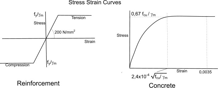
2) The compressive stresses in concrete are derived from stress strain curve shown below with γ m = 1,5
3) The tensile strength of concrete is ignored
4) The stresses in the reinforcement are derived from the stress/strain curve as shown below γ m = 1,15
5) When the section is resisting only flexure the lever arm should not be greater than 0,95x the effective depth
The effective depth is the depth from the compression face to the centre of the area of the main reinforcement group
Formwork
The formwork is the timber , steel or plastic moulds into which the concrete is poured
on site to create the various concrete components. It is a vital part of the construction process
and the formwork costs can be up to 50% of the concrete construction costs. The reinforcement
must be located in the formword prior to pouring the concrete.
The formwork must be leaktight, strong and rigid to contain and maintain dimensions of the full liquid concrete mass. It must also be designed
for standardisation and reuse to reduce the construction costs to a minimum.
It is clear that the formwork should not only be designed for construction it should also include features
allowing safe and convenient removal and re-use
Relevant Standards
The design notes provided on this page relate to BS 8110-1 :1997 which has been superseded by the standards referenced below.
| Code Reference Number | Title |
| BS EN 1992-1-1:2004 | General rules and rules for buildings..Replaces BS 8110-1, BS 8110-2 and BS 8110-3 |
| BS EN 1992-1-2:2004 | Eurocode 2:General rules. Structural fire design |
| BS EN 1992-2:2005 | Eurocode 2:Concrete bridges. Design and detailing rules..Replaces BS 5400-4, BS 5400-7 and BS 5400-8 |
| BS EN 1992-3:2006 | Eurocode 2:Liquid retaining and containing structures...Replaces BS 8007 |
| BS EN 1992-3:2006 | Eurocode 2:Liquid retaining and containing structures...Replaces BS 8007 |
| BS EN 206-1:2000 | Concrete. Specification, performance, production and conformity |
| BS EN 206-9:2010 | Concrete. Additional rules for self-compacting concrete (SCC)y |
symbols
A s = Area of tension reinforcement
A' s = Area of Compression reinforcement
b = width or effective width of section
b w = average width of web
d = effective depth of section (compression face to centre of reinforcement )
d' = depth to compression reinforcement
h f = thickness of flange
L = effective span of beam
M = Design Ultimate moment at section
x = Depth to neutral axis
z = lever arm
f cu =Characteristic strength for concrete ( f cu ) = cube strength
M u = Ultimate moment capacity of unreinforced beam
βb = ratio (Moment at the section after redistribution)/
(Moment at the section before redistribution)
γ m partial factor of safety applied to characteristics strengths of concrete and reinforcement
A c = Area of concrete at section
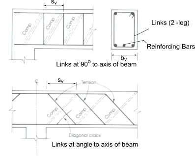
A sv = Total cross section area of links at the neutral axis , at section
f y =Characteristic strength of reinforcement ..Proof /yield strength
f yv =Characteristic strength of links ..Proof /yield strength
s v= spacing of links along section
V = design shear force at ultimate loads
v = Design shear stress at cross section
v c = Design shear capacity
Columns..................
A c = net cross section area of concrete in column
A sc = Area of vertical reinforcement
a u = deflection at ULS
b = width of column section (smallest cross section dimension
h = depth of column section
l e = effective height of column
l o = clear height of column between restraints
l c = centre height of column between restraint centres
M 1= Smaller initial end moment due to design ultimate loads
M 2= Larger initial end moment due to design ultimate loads
N = design ultimate axial load on column
N bal = design ultimate axial load of a balanced section : (if symmetrically reinforced assume 0,25f cubd )
Walls..................
e a = additional eccentricity due to deflections
e x = resultant eccentricity of load at right angles to plane of wall
e x1 = resultant eccentricity at top of wall
e x2 = resultant eccentricity at bottom of wall
h = thickness of wall
l e = effective height of wall
l o = clear height of wall between lateral supports
Slabs
V eff = Effective shear force at ultimate loads and moments
U = Shear perimeter around column head.
U o = shear perimeter around column head at column face
U i = shear perimeter around column head location away from column face. (see notes.)
|
Concrete building components
Beams
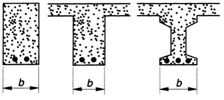
Beams are horizontal structural items specifically design to support vertical loads . Concrete beams are generally rectangular in
section with width b and height h and length L. Beams can also be of a variety of section including channel section, tee section, I section etc.
There are a number of support configurations for beams including cantilever, simply supported , continuous, etc each one tending to produce
different stress and deflection characteristics. As concrete is not able to withstand tensile stress , loaded concrete beams are generally reinforced
in the area under tensile stress.
Concrete columns
Vertical structural elements of clear height = l and cross section = b x h where h < 4b are columns , otherwise they are walls.
A column should not have an unrestrained length greater than than 60b.
Concrete Walls
Vertical load bearing element with length exceeding 4 times the thickness. The clear height is designated l o and
the thickness h. Concrete walls can be plain walls which have zero to minimum reinforcement (< 0,4% of section area ) or reinforced
walls with reinforcemnt > 0,4% of area .
Flat Slabs
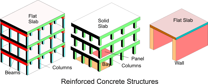
Flat slabs are horizontal slabs , used for floors or upper structural surface which are supported on walls or beams.
Solid Slabs
These are horizontal slabs supported on pads or columns instead of walls
Rough preliminary sizing of concrete elements
| Element | Typical spans
(m) | Overall Depth or Thickness |
| Simply supported | Continuous | Cantilever |
| One way spanning slabs | 5 - 6 | L /(22-30) | L/(28-36) | L/(7-10) |
| Two way spanning slabs | 6-11 | L /(24-35) | L/(34-40) | - |
| Flat slabs | 4-8 | L /27 | L/36 | L/(7-10) |
| Rectangular beams | 9-10 | L /12 | L/15 | L/6 |
| Flanged beams | 5-15 | L /10 | L/12 | L/6 |
| Columns | 2,5 -8 | H / (10-20) | H / (10-20) | H/10 |
| Walls | 2-4 | H / (30-35) | H / 45 | H/ (15-18) |
L = effective span = smaller of distance between bearing centres or clear distance (between supports ) + depth of section
Partial Safety margins....
Typical Values of γ m for Ultimate limit state... (Persistent and transient)
| Reinforcement & Pre stressing | 1,15 |
| Concrete in flexure or axially loaded | 1,5 |
| Shear strength without reinforcement | 1,25 |
| others | => 1,5 |
Load Combinations and values γ f for Ultimate limit state.
| Load combinations |
Load type |
| Dead ( G k) |
Imposed ( Q k) |
Earth + Water Pressure |
Wind Pressure |
Adverse | Beneficial |
Adverse | Beneficial |
| Dead and Imposed (+ earth and water pressure) |
1,4 | 1,0 | 1,6 | 0 | 1,6 | 1,2 |
| Dead and Wind (+ earth and water pressure) |
1,4 | 1,0 | - | - | 1,2 | 1,4 |
| Dead + Imposed + Wind (+ earth and water pressure) |
1,2 | 1,2 | 1,2 | 1,2 | 1,2 | 1,2 |
Simple Reinforced beam design
The theory supporting the relationships in this section,in outline, is covered on web page Reinforced concrete
beams theory
The sketch below identifies the types of simple reinforced beams that are relevant to the notes provided
Condition of strain and stress in a rectangular section
at ultimate limit state of loading is shown in the figure below
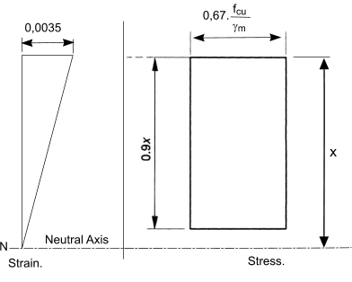
Note: The factor 0,67 is not a partial safety margin it relates to the direct relationship between the
cube strength as indicated by f cu and the strength in flexure of the concrete.
The total compressive force generated within the concrete at the ultimate moment capacity is
0,9 . 0,67.fcu . b . x / (γ m =1,5) = 0,4 . fcu. b. x
The ultimate moment capacity of a unreinforced concrete beam section where there is less than 10% moment distribution is
M u = 0,156 .F cu.b.d2
M = K.[ f cu.b.d2 ]
Factors for lever arm (z) and neutral axis depth (x)
| x | 0,13.d | 0,15.d | 0,19.d |
0,25d |
0,32.d | 0,39.d | 0,45.d | 0,5.d |
| z | 0,942.d | 0,933.d | 0,91.d | 0,887.d | 0,857.d | 0,825.d |
0,798.d | 0,775.d |
| K | 0,05 | 0,057 | 0,070 | 0,090 | 0,110 | 0,130 | 0,145 | 0,156 |


Area of Reinforcement bars
If the applied moment is less than M u then the area of tension reinforcement =

If the applied moment is greater than M u ( K > 0,156 ) then tension and compression
reinforcement is necessary
The tension reinforcement required is.

Compression reinforcement required is

Application of equations to concrete tees
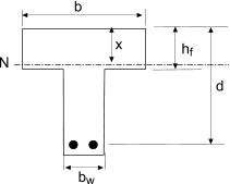
Mu is simply calculated as 0,4.fcu.b.hf.(d - hf/2) if this is greater than M then the neutral axis
is within the flange and the tee can be assessed using the equations above..
Shear Strength of concrete beams
The design shear capactity (v) in a concrete beam at any section is calculated from
v = V / (b v.d )
V is the Shear force at a section
v should never exceed 0,8 √ f cu or 5 N/mm2 if lower.
Values of concrete shear capacity v c related to % reinforcement and effective depth (d) of section
% Reinforcement
=
100 A s /b v.d |
Effective Depth (mm) - d
| | 125 | 150 | 175 | 200 | 225 | 250 | 300 | 400 |
| N/mm2 | N/mm2 |
N/mm2 | N/mm2 |
N/mm2 | N/mm2 |
N/mm2 | N/mm2 |
| = < 0,15 | 0,45 | 0,43 | 0,41 | 0,40 | 0,39 | 0,38 | 0,36 | 0,34 |
| 0,25 | 0,53 | 0,51 | 0,49 | 0,47 | 0,46 | 0,45 | 0,43 | 0,40 |
| 0,50 | 0,67 | 0,64 | 0,62 | 0,60 | 0,58 | 0,56 | 0,54 | 0,50 |
| 0,75 | 0,77 | 0,73 | 0,71 | 0,68 | 0,66 | 0,65 | 0,62 | 0,57 |
| 1,00 | 0,84 | 0,81 | 0,78 | 0,75 | 0,73 | 0,71 | 0,68 | 0,63 |
| 1,50 | 0,97 | 0,92 | 0,89 | 0,86 | 0,83 | 0,81 | 0,78 | 0,72 |
| 2,0 | 1,06 | 1,02 | 0,98 | 0,95 | 0,92 | 0,89 | 0,86 | 0,80 |
| >= 3,0 | 1,22 | 1,16 | 1,12 | 1,08 | 1,05 | 1,02 | 0,98 | 0,91 |
Form of Shear Reinforcement
If the applied shear stress is less than 0,5 v c throughout the beam then
Minimum links should be provided, and in elements of low importance e.g lintels then no links need be included
Suggested shear area provided = A sv > 0,2 b v.s v / (0,87 .f yv)
If the applied shear stress is greater than 0,5 v c and less than (0,4 + v c) throughout the beam then
Minimum links should be provided for the whole length of beam to provide shear resistance of 0,4 N/mm2
Suggested shear are provided = A sv > 0,4 b v.s v / (0,87 . f yv)
If the applied shear stress is greater than (0,4 + v c) and less than (0,8 Sqrt(F cu or 5 N/mm2) + v c) throughout the beam then
Links should be provided for the whole length of beam to provide shear resistance at no more than 0,75d spacing . No tension bar should be more the 150 mm for a vertical shear link.
Suggested shear are provided = A sv > b v.s v (v - v c) / (0,87 . f yv)
 > >
Stiffness and Deflection
A table is provided below which gives the basic span/ depth ratio for beams which limit the total
deflection to span/250 or 20mm (if less) , for spans up to 10m.
| Type | Rectangular Section | Flanged Section |
| b w/b =1,0 | b w/b =< 0,3 |
| Cantilever | 7 | 5,6 |
| Simply support | 20 | 16,0 |
| Continuous | 26 | 20,8 |
For b w/b >0,3 interpolation between the rectangular and flanged values is acceptable
Allowable span/depth ratio
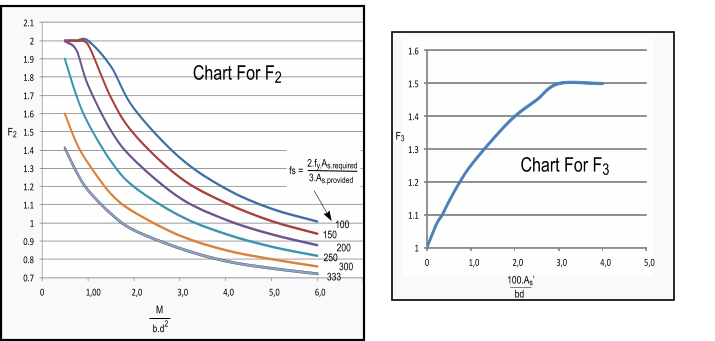
The allowable span/depth = F 1.F 2F 3F 4. Basic span/depth ratio
F 1 For long spans exceeding 10m the values in the table should be multiplied by 10/span.
F 2= A factor to allow for tension reinforcement. See chart below
F 3= A factor to allow for compression reinforcement. See chart below
F 4= A factor to allow for stair waists where the staircase occupies over 60% of the span
Simple Column design
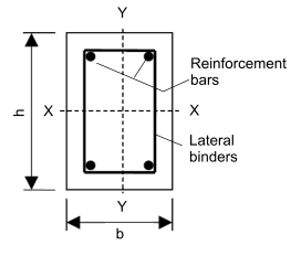
Cross section of a typical simple column.
A column should not have a clear distance between restraints which exceeds 60.b ( b being the small cross section dimension ).
If one end of a column is not restrained (a cantilever column) then its clear height must be the smaller of 60.b or 100.b2 /h .
It is important early in the design process to determine if the column is a stocky design and if there is significant bracing
associated with the columns. The effective length of a column l e = l o.β
where β is the effective length constant which is dependent on the end support conditions (see tables below).
A column is considered a stocky column if its effective length divided by b = l e/b is less than 15.
A longer column must be assessed in the design for risk of buckling.
Some simple rules for column reinforcement.
A sc should by more than 1% and less than 6% of gross cross section area of column (b x h)
The minimum dia of bars should be 12mm.
Lateral binders/ties should be arranged to restrain each bar from buckling and the end of the binders should be
anchored. The pitch of the binder should not exceed b or 12 times the dia of the longitudinal bars, nor 300 mm .
The diameter of the binders
should not be less than 25% of the diameter of the longitudinal bars
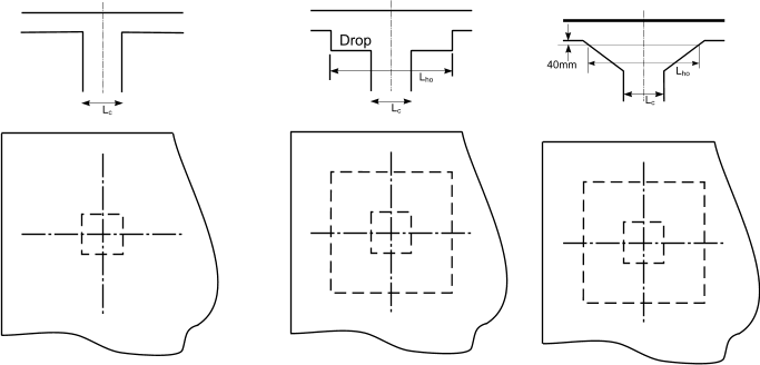
Typical column head designs. (columns and associated heads
can also be circular.
Braced Columns -Table of effective length coefficients (β)
A column is considered to be braced if lateral stability is provided by walls or buttresses. The column is effectively
only taking axial loads and moments resulting from eccentricity of lateral loads
| End Condition at Top | End Condition at Bottom |
| Rigidly Fixed | Fixed | Pinned with some
angular restraint |
| Rigidly Fixed | 075 | 0,80 | 0,90 |
| Fixed | 0,80 | 0,85 | 0,95 |
Pinned with some
angular restraint | 0,9 | 0,95 | 1,00 |
Unbraced Columns -Table of effective length coefficients (β)
| End Condition at Top | End Condition at Bottom |
| Rigidly Fixed | Fixed | Pinned with some
angular restraint |
| Rigidly Fixed | 1,2 | 1,3 | 1,6 |
| Fixed | 1,3 | 1,5 | 1,8 |
Pinned with some
angular restraint | 1,6 | 1,8 | - |
| Free | 2,2 | - | - |
Rigidly Fixed
The end of the column is connected monolithically (solidly) to beams on either side which are at least
as deep as the overall dimension of the column in the plane considered. Where the column is connected to a foundation
structure, this should be of a form specifically designed to carry moments.
Fixed.
The end of the column is connected monolithically to beams or slabs on either side which are shallower than the overall dimension of the column
in the plane considered
Pinned with some angular restraint
The end of the column is connected to members which, while not specifically designed to provide restraint to rotation of the column will, nevertheless,
provide some nominal restraint.
Free.
The end of the column is unrestrained against both lateral movement and rotation. e.g the free end of a cantilever column in an unbraced structure
Design Calculations
When a stocky column is subject to a simple axial loads with induced moments , assuming a well balanced load scenario , it
need only be design for the ultimate design axial force + a nominal allowance for an eccentricity of force (e c ) of h/20 (with a maximum of 20mm).
When a stocky column is subject Axial forces and bending stresses it is generally necessary to use
design charts .Reference Column Design charts.
Stocky beams resisting moments
Following equations include provision for γ m.
When a stocky column cannot be subjected to significant moments,it is sufficient to design the
column such that the design ultimate load is less than
N = 0,4 f cu.A c + 0,75 A sc.f y
When a stocky column is supporting to a reasonably symmetrical arrangement of beams of similar spans and which are for uniformly distributed loads , it is sufficient to design the
column such that the design ultimate load is less than
N = 0,35 f cu.A c + 0,67 A sc.f y
Biaxial bending in columns
When it is necessary to consider biaxial moments, the design moment about one axis is enhanced to allow for the biaxial loading
condition and the column is designed around the enhanced axis. Consider the column as loaded below.
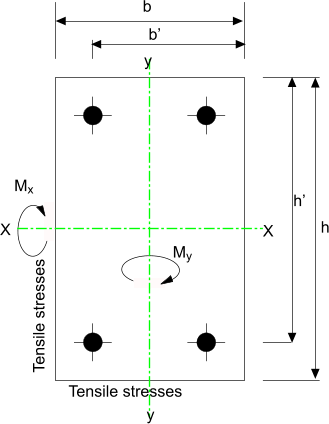
The relevant moment is modified as below

| N/( b.h.F cu ) | 0 | 0,10 | 0,20 | 0,30 | 0,40 | 0,50 | >=0,60 |
| β a | 1,0 | 0,88 | 0,77 | 0,65 | 0,53 | 0,42 | 0,3 |
Design of Walls
The design axial forces in a reinforced wall may be calculated on the assumption
that the beam and floor slabs being supported are simply supported.
The effective length of a wall l e should be obtained as if the wall was a column which is subject
to moments in the plane normal to the wall. The determination if a wall is stocky or slender is also obtained
using the same criteria as for a column.
Stocky reinforced walls
A stocky braced reinforced wall supporting reasonably symmetrical load should be designed such than..
n w = 0,55.f cu.A c + f y.0,67A SC.
n w = total design axial load on wall due to design ultimate loads :providing the slab loads
are uniform in loading and relatively evenly distributed.
Except for short braced walls loaded symmetrically the eccentricity in the direction at right angles to a wall
should not be less than h/20 or 20mm if less.
When the eccentricity results from only transverse moments the design axial load may be assumed to be evenly distributed
along the length of the wall. The cross section should be designed to resist the design ultimate load and the transverse moment . The assumptions
made for the calculation of beam sections apply.
When a wall is subject to in-plane moments and uniform axial forces the cross section of the wall should be designed to support
the ultimate resulting axial loads and inplane moments.
Slender reinforced walls
The maximum slenderness ratio l e/h should be 40 for braced walls with <1% reinforcement: 45 for braced walls with => 1%
reinforcement: 30 for unbraced walls
A suitable design procedure is to first consider axial forces and in-plane moments to obtain the distribution of forces along
the wall assuming the concrete does not resist tension. The transverse moments are then calculated. At various points along the wall
the results are combined.
Walls subject to significant transverse moments additional to the ones allowed for by assuming a minimum eccentricity are considered by assuming such
walls are slender columns bent about the minor axis . If the wall is reinforced with only one central layer of reinforcement the additional moments should
be doubled
Plain walls
Plain walls include less than 0,4% reinforcement.
The effective height of plain unbraced concrete walls is assessed as ( l e = 1,5 l o ) if the wall is supporting a roof or floor slab, otherwise it is
calculated as (l e = 2 l o).
When a plain concrete wall is braced with lateral supports resisting both rotation and movement then ( l e = 0,75 l o )
Where the lateral support only resists lateral movement then ( l e = l o )or if relevant ( l e = 2,5 (distance between support and a free edge )
Design of solid slabs
Solid slabs can be simply one-way loaded plates or two way loaded plates depending on the support arrangements
Design Moments and shear forces in simple one way spanning continuous slabs
Uniformly Distributed Loads
F = Total Design Ultimate load on one slab (1,4 G k + 1,6 Q k)
l s = is effective span of slab
G k = Dead Load
Q k = Imposed load)
Design Moments and shear forces in simple one way spanning continuous slabs
| | End support/ Slab connection |
At First Support |
At Middle of interior span | At Interior supports |
| Simple Supports | Continuous |
| Outer Supports | Near Middle of end span | Outer Supports | Near Middle of end span |
| Moment | 0 | F.l s /11,5 | -F.l s /25 | F.l s /13 | -F.l s /11,5 |
FL /15,5 | -F.l s /15,5 |
| Shear | F / 2,5 | - | 6 F /13 | - | 3 F /5 |
- | F/2 |
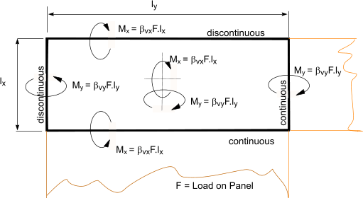
Design Moments and shear forces in two way spanning continuous slabs
Uniformly Distributed Loads
| Type of Panel and Location | Short span coefficient β sx |
Long span coefficient β sy |
| For values of l y/l x |
| 1,0 | 1,1 | 1,2 | 1,3 | 1,4 | 1,5 | 1,75 | 2,0 |
| Interior Panels
| | Moment at continuous edge | -0,031 | -0,037 | -0,042 | -0,046 | -0,050 | -0,053 | -0,059 | -0,063 | -0,032 |
| Moment at mid-span | 0,024 | 0,028 | 0,032 | 0,035 | 0,037 | 0,040 | 0,044 | 0,048 | 0,024 |
| One short edge discontinuous
| | Moment at continuous edge | -0,039 | -0,044 | -0,048 | -0,052 | -0,055 | -0,058 | -0,063 | -0,067 | -0,037 |
| Moment at mid-span | 0,029 | 0,033 | 0,036 | 0,039 | 0,041 | 0,043 | 0,047 | 0,050 | 0,028 |
| One long edge discontinuous
| | Moment at continuous edge | -0,039 | -0,049 | -0,056 | -0,062 | -0,068 | -0,073 | -0,082 | -0,089 | -0,037 |
| Moment at mid-span | 0,030 | 0,036 | 0,042 | 0,047 | 0,051 | 0,055 | 0,062 | 0,067 | 0,028 |
| Two adjacent edges discontinuous
| | Moment at continuous edge | -0,047 | -0,056 | -0,063 | -0,069 | -0,074 | -0,078 | -0,087 | -0,093 | -0,045 |
| Moment at mid-span | 0,036 | 0,042 | 0,047 | 0,051 | 0,055 | 0,059 | 0,065 | 0,070 | 0,034 |
| Two short edges discontinuous
| | Moment at continuous edge | -0,046 | -0,050 | -0,054 | -0,057 | -0,060 | -0,062 | -0,067 | -0,070 | - |
| Moment at mid-span | 0,034 | 0,038 | 0,040 | 0,043 | 0,045 | 0,047 | 0,050 | 0,053 | 0,034 |
| Two long edges discontinuous
| | Moment at continuous edge | - | - | - | - | - | - | - | - | -0,045 |
| Moment at mid-span | 0,034 | 0,046 | 0,056 | 0,065 | 0,072 | 0,078 | 0,091 | 0,10 | 0,034 |
| Three edges discontinuous-1 long edge discontinuous
| | Moment at continuous edge | -0,057 | -0,065 | -0,071 | -0,076 | -0,081 | -0,084 | -0,092 | -0,098 | - |
| Moment at mid-span | 0,043 | 0,048 | 0,053 | 0,057 | 0,060 | 0,063 | 0,069 | 0,074 | 0,044 |
| Three edges discontinuous- 1 short discontinuous
| | Moment at continuous edge | - | - | - | - | - | - | - | - | -0,058 |
| Moment at mid-span | 0,042 | 0,054 | 0,063 | 0,071 | 0,078 | 0,084 | 0,096 | 0,105 | 0,044 |
| Four edges discontinuous
| | Moment at mid-span | 0,055 | 0,065 | 0,074 | 0,081 | 0,087 | 0,092 | 0,103 | 0,111 | 0,056 |
Design Moments and shear forces in two way spanning continuous slabs
Shear Force coefficients
| Type of Panel and Location | Short span coefficient βsx |
Long span coefficient βvy |
| For values of ly/lx |
| 1,0 | 1,1 | 1,2 | 1,3 | 1,4 | 1,5 | 1,75 | 2,0 |
| Interior Panels Four Edges continuous
| | Continuous edge | 0,33 | 0,36 | 0,39 | 0,41 | 0,43 | 0,45 | 0,48 | 0,50 | 0,33 |
| One short edge discontinuous
| | Continuous edge | 0,36 | 0,39 | 0,42 | 0,44 | 0,45 | 0,47 | 0,50 | 0,52 | 036 |
| Discontinuous Edge | - | - | - | - | - | - | - | - | 0,24 |
| One long edge discontinuous
| | Continuous edge | 0,36 | 0,40 | 0,44 | 0,49 | 0,51 | 0,55 | 0,59 | 0,36 | -0,037 |
| Discontinuous Edge | 0,24 | 0,27 | 0,29 | 0,32 | 0,34 | 0,36 | 0,38 | - | 0,028 |
| Two adjacent edges discontinuous
| | Continuous edge | 0,40 | 0,44 | 0,47 | 0,50 | 0,52 | 0,54 | 0,57 | 0,60 | 0,40 |
| Discontinuous Edge | 0,26 | 0,29 | 0,31 | 0,33 | 0,34 | 0,35 | 0,38 | 0,40 | 0,26 |
| Two short edges discontinuous
| | Continuous edge | 0,40 | 0,43 | 0,45 | 0,47 | 0,48 | 0,49 | 0,52 | 0,54 | - |
| Discontinuous Edge | - | - | - | - | - | - | - | - | 0,26 |
| Two long edges discontinuous
| | Continuous edge | - | - | - | - | - | - | - | - | 0,40 |
| Discontinuous Edge | 0,26 | 0,30 | 0,33 | 0,36 | 0,38 | 0,40 | 0,44 | 0,47 | - |
| Three edges discontinuous-1 long edge discontinuous
| | Continuous edge | 0,45 | 0,48 | 0,51 | 0,53 | 0,55 | 0,57 | 0,60 | 0,63 | - |
| Discontinuous Edge | 0,30 | 0,32 | 0,34 | 0,35 | 0,36 | 0,37 | 0,39 | 0,41 | 0,29 |
| Three edges discontinuous- 1 short discontinuous
| | Continuous edge | - | - | - | - | - | - | - | - | 0,45 |
| Discontinuous Edge | 0,29 | 0,33 | 0,36 | 0,38 | 0,40 | 0,42 | 0,45 | 0,48 | 0,30 |
| Four edges discontinuous
| | Discontinuous Edge | 0,33 | 0,36 | 0,39 | 0,41 | 0,43 | 0,45 | 0,48 | 0,50 | 0,33 |
Deflection .
The deflection can be limited by the application of the span/depth ratio as indicated in the table for
beams and modified by the use of F2 as shown in the relevant graph Design of Beams...... Only conditions at the centre of slab in the width
of the should be used to influence the deflection.
For two way spanning slabs the ratio should be based on the shorter span.
Design of Flat Slabs
Flat slabs should be designed to satisfy deflection requirements and to resist the shear
load around the column supports.
BS 8110 allows for a simplified method for determining moments subject to certain provisions
1) design is based on a single load case of all spans being loaded with
the maximum design ultimate load.
2) There are at least three rows of panels of approx equal span in the direction under consideration
4)The ratio of imposed to dead load does not exceed 1,25
5)The characteristic imposed load does not exceed 5kN/m2
This method involve simply using the table provided for design moments in simple one way spanning continuous slabs
as provided above as copied below.
Moments at supports resulting from the table below are reduced by 0,15F.h c
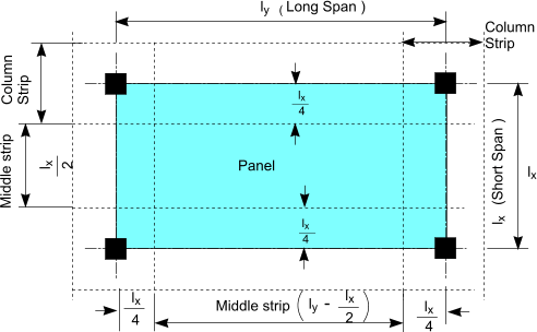
The design moments resulting should be divided between the column strips and
mid-strips as shown in the figure below in proportions as shown in table below
F = Total Design Ultimate load (1,4 G k + 1,6 Q k)
l s = is effective span of slab G k = Dead Load
Q k = Imposed load)
| | End support/ Slab connection |
At First Support |
At Middle of interior span | At Interior supports |
| Simple Supports | Continuous |
| Outer Supports | Near Middle of end span | Outer Supports | Near Middle of end span |
| Moment (M) | - | F.l s /11,5 | -F.l s /25 | F.l s /13 | -F.l s /11,5 |
FL /15,5 | -F.l s /15,5 |
| Distribution of design moments across panels in flat slabs |
| Design Moment |
apportionment between strips
as a percentage
of total negative
or positive moments |
| Column strip % | Middle Strip strip % |
| negative | 75 | 25 |
| positive | 55 | 45 |
|
|
Punching shear forces in Flat Slabs
The critical shear condition for flat slabs is punching shear around the column heads.
The shear load supported by a column is the basic calculated shear force (V) uprated to account for moment transfer.
For slabs with approximately equal spans the uprated shear force, designated the effective shear force V eff ,can be simply estimated using the following rules.
For internal columns V eff = 1,15 V
For corner columns V eff = 1,15 V
For corner columns V eff = 1,15 V
For edge columns with the moment parallel to the edge V eff = 1,25 V
For edge columns with the moment normal to the edge V eff = 1,4 V
The slab shear at the column face is calculated as

d = thickness of slab and U o is the perimeter of the slab at the column head edge
ν o should be less than 0,8 √ f cu or 5 N/mm2 if less
Perimeters U i radiating out from the column edge should be checked with the first perimeter (i =1)
at a distance 1,5.d from the column face and subsequent perimeters i = 2,3... with intervals of 0,75.d

successive perimeters are checked until the applied shear stressν i is less
than the allowable shear stress ν c. Reinforcement links are required between
the perimeters at which the shear stress is greater than ν c.
Deflection .
When the gross width of drops in both directions exceed 1/3 the respective span the deflection can be limited by the application of the span/depth ratio as indicated in the table for
beams Design of Beams...... Otherwise the resulting span/effective depth should be multiplied by 0,9.
The assessment should be completed for the most critical direction.
Reinforcement Data
Cross sectional area of number of bars ( mm2 )
| Bar Size (mm) | Cross sectional area of number of bars (mm2) |
| 1 | 2 | 3 | 4 | 5 | 6 | 7 | 8 | 9 | 10 | 11 | 12 |
| 6 | 28 | 57 | 85 | 113 | 141 | 170 | 198 | 226 | 254 | 283 | 311 | 339 |
| 8 | 50 | 101 | 151 | 201 | 251 | 302 | 352 | 402 | 452 | 503 | 553 | 603 |
| 10 | 79 | 157 | 236 | 314 | 393 | 471 | 550 | 628 | 707 | 785 | 864 | 942 |
| 12 | 113 | 226 | 339 | 452 | 565 | 679 | 792 | 905 | 1018 | 1131 | 1244 | 1357 |
| 16 | 201 | 402 | 603 | 804 | 1005 | 1206 | 1407 | 1608 | 1810 | 2011 | 2212 | 2413 |
| 20 | 314 | 628 | 942 | 1257 | 1571 | 1885 | 2199 | 2513 | 2827 | 3142 | 3456 | 3770 |
| 25 | 491 | 982 | 1473 | 1963 | 2454 | 2945 | 3436 | 3927 | 4418 | 4909 | 5400 | 5890 |
| 32 | 804 | 1608 | 2413 | 3217 | 4021 | 4825 | 5630 | 6434 | 7238 | 8042 | 8847 | 9651 |
| 40 | 1257 | 2513 | 3770 | 5027 | 6283 | 7540 | 8796 | 10053 | 11310 | 12566 | 13823 | 15080 |
| 50 | 1963 | 3927 | 5890 | 7854 | 9817 | 11781 | 13744 | 15708 | 17671 | 19635 | 21598 | 23562 |
Cross sectional area of number of bars ( mm2 ) per metre spacing
| Bar Size ( mm ) | Bar Spacing |
| 50 | 75 | 100 | 125 | 150 | 175 | 200 | 225 | 250 | 275 | 300 | 400 |
| 6 | 565 | 377 | 283 | 226 | 188 | 162 | 141 | 126 | 113 | 103 | 94 | 71 |
| 8 | 1005 | 670 | 503 | 402 | 335 | 287 | 251 | 223 | 201 | 183 | 168 | 126 |
| 10 | 1571 | 1047 | 785 | 628 | 524 | 449 | 393 | 349 | 314 | 286 | 262 | 196 |
| 12 | 2262 | 1508 | 1131 | 905 | 754 | 646 | 565 | 503 | 452 | 411 | 377 | 283 |
| 16 | 4021 | 2681 | 2011 | 1608 | 1340 | 1149 | 1005 | 894 | 804 | 731 | 670 | 503 |
| 20 | 6283 | 4189 | 3142 | 2513 | 2094 | 1795 | 1571 | 1396 | 1257 | 1142 | 1047 | 785 |
| 25 | 9817 | 6545 | 4909 | 3927 | 3272 | 2805 | 2454 | 2182 | 1963 | 1785 | 1636 | 1227 |
| 32 | - | 10723 | 8042 | 6434 | 5362 | 4596 | 4021 | 3574 | 3217 | 2925 | 2681 | 2011 |
| 40 | - | - | 12566 | 10053 | 8378 | 7181 | 6283 | 5585 | 5027 | 4570 | 4189 | 3142 |
| 50 | - | - | 19635 | 15708 | 13090 | 11220 | 9817 | 8727 | 7854 | 7140 | 6545 | 4909 |
Link reinforcement in beams, Asv/sv ( mm2/mm ) - 2 legs
| Bar Size (mm) |
Link reinforcement in beams, Asv/sv (mm2/mm) - 2 legs |
| Spacing of Links (mm) |
| 50 | 75 | 100 | 125 | 150 | 175 | 200 | 225 | 250 | 275 | 300 | 400 |
| 6 | 1.13 | 0.75 | 0.57 | 0.45 | 0.38 | 0.32 | 0.28 | 0.25 | 0.23 | 0.21 | 0.19 | 0.14 |
| 8 | 2.01 | 1.34 | 1.01 | 0.80 | 0.67 | 0.57 | 0.50 | 0.45 | 0.40 | 0.37 | 0.34 | 0.25 |
| 10 | 3.14 | 2.09 | 1.57 | 1.26 | 1.05 | 0.90 | 0.79 | 0.70 | 0.63 | 0.57 | 0.52 | 0.39 |
| 12 | 4.52 | 3.02 | 2.26 | 1.81 | 1.51 | 1.29 | 1.13 | 1.01 | 0.90 | 0.82 | 0.75 | 0.57 |
| 16 | 8.04 | 5.36 | 4.02 | 3.22 | 2.68 | 2.30 | 2.01 | 1.79 | 1.61 | 1.46 | 1.34 | 1.01 |
Link reinforcement in beams, Asv/sv ( mm2/mm ) - 3 legs
| Bar Size (mm) | Link reinforcement in beams, Asv/sv (mm2/mm) - 3 legs |
| Spacing of Links (mm) |
| 50 | 75 | 100 | 125 | 150 | 175 | 200 | 225 | 250 | 275 | 300 | 400 |
| 6 | 1.70 | 1.13 | 0.85 | 0.68 | 0.57 | 0.48 | 0.42 | 0.38 | 0.34 | 0.31 | 0.28 | 0.21 |
| 8 | 3.02 | 2.01 | 1.51 | 1.21 | 1.01 | 0.86 | 0.75 | 0.67 | 0.60 | 0.55 | 0.50 | 0.38 |
| 10 | 4.71 | 3.14 | 2.36 | 1.88 | 1.57 | 1.35 | 1.18 | 1.05 | 0.94 | 0.86 | 0.79 | 0.59 |
| 12 | 6.79 | 4.52 | 3.39 | 2.71 | 2.26 | 1.94 | 1.70 | 1.51 | 1.36 | 1.23 | 1.13 | 0.85 |
| 16 | 12.06 | 8.04 | 6.03 | 4.83 | 4.02 | 3.45 | 3.02 | 2.68 | 2.41 | 2.19 | 2.01 | 1.51 |
Link reinforcement in beams, Asv/sv ( mm2/mm ) - 4 legs
| Bar Size (mm) | Link reinforcement in beams, Asv/sv (mm2/mm) - 4 legs |
| Spacing of Links (mm) |
>| 50 | 75 | 100 | 125 | 150 | 175 | 200 | 225 | 250 | 275 | 300 | 400 |
| 6 | 2.26 | 1.51 | 1.13 | 0.90 | 0.75 | 0.65 | 0.57 | 0.50 | 0.45 | 0.41 | 0.38 | 0.28 |
| 8 | 4.02 | 2.68 | 2.01 | 1.61 | 1.34 | 1.15 | 1.01 | 0.89 | 0.80 | 0.73 | 0.67 | 0.50 |
| 10 | 6.28 | 4.19 | 3.14 | 2.51 | 2.09 | 1.80 | 1.57 | 1.40 | 1.26 | 1.14 | 1.05 | 0.79 |
| 12 | 9.05 | 6.03 | 4.52 | 3.62 | 3.02 | 2.59 | 2.26 | 2.01 | 1.81 | 1.65 | 1.51 | 1.13 |
| 16 | 16.08 | 10.72 | 8.04 | 6.43 | 5.36 | 4.60 | 4.02 | 3.57 | 3.22 | 2.92 | 2.68 | 2.01 |
mesh reinforcement in beams, Asv/sv ( mm2/mm ) - 4 legs
| BS4483 Fabric | Mesh size nominal pitch of wires |
Diameter of wire |
Cross section area per metre width |
Nominal mass | No. of sheets |
| Main | Cross | Main | Cross | Main |
Cross | per tonne | - |
| mm | mm | mm | mm |
mm2(/sup> | mm2(/sup> | kg/m� | - |
| Square mesh |
| A393 | 200 | 200 | 10 | 10 | 393 | 393 | 6.16 | 15 |
| A252 | 200 | 200 | 8 | 8 | 252 | 252 | 3.95 | 22 |
| A193 | 200 | 200 | 7 | 7 | 193 | 193 | 3.02 | 22 |
| A142 | 200 | 200 | 6 | 6 | 142 | 142 | 2.22 | 40 |
| A98 | 200 | 200 | 5 | 5 | 98 | 98 | 1.54 | 57 |
| Structural mesh |
| B1131 | 100 | 200 | 12 | 8 | 1131 | 252 | 10.9 | 8 |
| B785 | 100 | 200 | 10 | 8 | 785 | 252 | 8.14 | 11 |
| B503 | 100 | 200 | 8 | 8 | 503 | 252 | 5.93 | 15 |
| B385 | 100 | 200 | 7 | 7 | 385 | 193 | 4.53 | 20 |
| B283 | 100 | 200 | 6 | 7 | 283 | 193 | 3.73 | 24 |
| B196 | 100 | 200 | 5 | 7 | 196 | 193 | 3.05 | 29 |
| Long mesh |
| C785 | 100 | 400 | 10 | 6 | 785 | 70.8 | 6.72 | 13 |
| C636 | 100 | 400 | 9 | 6 | 636 | 70.8 | 5.55 | 16 |
| C503 | 100 | 400 | 8 | 5 | 503 | 49 | 4.34 | 21 |
| C385 | 100 | 400 | 7 | 5 | 385 | 49 | 3.41 | 26 |
| C283 | 100 | 400 | 6 | 5 | 283 | 49 | 2.61 | 34 |
| Wrapping mesh |
| D98 | 200 | 200 | 5 | 5 | 98 | 98 | 1.54 | 57 |
| D49 | 100 | 100 | 2.5 | 2.5 | 49 | 49 | 0.77 | 113 |
Nominal thick cover *(mm)of reinforcement bars for fire resistance (hours)
| Hours | Nominal thickness cover in mm |
| Beams | Floors |
Ribs | Columns |
| Simply Supported | Continuous |
Simply Supported | Continuous |
Simply Supported | Continuous |
Simply Supported |
| 0,5 | 20 | 20 | 20 | 20 | 20 | 20 | 20 |
| 1 | 20 | 20 | 20 | 20 | 20 | 20 | 20 |
| 1,5 | 20 | 20 | 25 | 20 | 35 | 20 | 20 |
| 2 | 40 | 30 | 35 | 25 | 45 | 35 | 25 |
| 3 | 60 | 40 | 45 | 35 | 55 | 45 | 25 |
| 4 | 70 | 50 | 55 | 45 | 65 | 55 | 25 |
Minimum Section width for fire resistance.
| Fire Resistance | Maximum beam width |
Rib Width |
Min floor Thickness | Column width |
Minimum Wall Thickness |
| Fully Exposed | 50% exposed | One Face Exposed |
p < 0,4% | 0,4% < p < 1% | p > 1% |
| h | mm | mm | mm | mm | mm |
mm | mm | mm | mm |
| 0,5 | 200 | 125 | 75 | 150 | 125 | 100 | 150 | 100 | 75 |
| 1,0 | 200 | 125 | 95 | 200 | 160 | 120 | 150 | 120 | 75 |
| 1,5 | 20 | 125 | 110 | 250 | 200 | 140 | 175 | 140 | 100 |
| 2,0 | 20 | 125 | 125 | 300 | 200 | 160 | - | 160 | 100 |
| 3,0 | 240 | 150 | 150 | 400 | 300 | 200 | - | 200 | 150 |
| 4,0 | 280 | 175 | 170 | 450 | 350 | 240 | - | 240 | 180 |
Characteristic strength of concrete
| Concrete strength classes |
| f ck | MPa (N/mm2) | 12 | 16 | 20 | 25 | 30 | 35 | 40 | 45 | 50 | 55 | 60 | 70 | 80 | 90 |
| f cu | MPa (N/mm2) | 15 | 20 | 25 | 30 | 37 | 45 | 50 | 55 | 60 | 67 | 75 | 85 | 95 | 105 |
| f cm | MPa (N/mm2) | 20 | 24 | 28 | 33 | 38 | 43 | 48 | 53 | 58 | 63 | 68 | 78 | 88 | 98 |
| E cm | GPa (N/mm2) | 27 | 29 | 30 | 31 | 33 | 34 | 35 | 36 | 37 | 38 | 39 | 41 | 42 | 44 |
Characteristic
strength ( f cu )
after 28 days |
Cube strength (N/mm2) at the age of: |
Flexural strength after 28 days | Indirect tensile strength at 28 days. |
Modulus of Elasticity |
| (N/mm2) | 1 days | 28 days | 2 month |
3 months | 6 months | 1 year |
(N/mm2) | (N/mm2) | (kN/mm2) |
| 15 | - | 15 | - | - | - | - | - | - | - |
| 20 | 13.5 | 20 | 22 | 23 | 24 | 25 | 2.3 | 1.5 | 24 |
| 25 | 16.5 | 25 | 27.5 | 29 | 30 | 31 | 2.7 | 1.8 | 25 |
| 30 | 20 | 30 | 33 | 35 | 36 | 37 | 3.1 | 2.1 | 26 |
| 40 | 28 | 40 | 44 | 45.5 | 47.5 | 50 | 3.7 | 2.5 | 30 |
| 50 | 36 | 50 | 54 | 55.5 | 57.5 | 60 | 4.2 | 2.8 | 32 |
Characteristic strength of Reinforcement
| Designation | Characteristic strength f y
N/mm2 |
Modulus of Elasticity E
kN/mm2 |
| Hot rolled Mild Steel | 250 | 200 |
| High Yield Steel (Hot or Cold Rolled) | 500 | 200 |
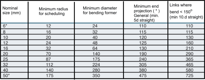
Reinforcement bar bending
Details based on BS 8666 .Normally grade H bars used f y = 500 N/m2


|


 >
>


