Control Index
Control System Stability
|
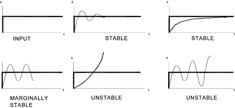
Introduction The stability of a control system is often extremely important and is generally a safety issue in the engineering of a system. An example to illustrate the importance of stability is the control of a nuclear reactor. An instability of this system could result in an unimaginable catastrophe. DefinitionsThe stability of a system relates to its response to inputs or disturbances.
A system which remains in a constant state unless affected by an external action
and which returns to a constant state when the external action is removed can be considered
to be stable. Control analysis is concerned not only with the stability of a system but also the degree of stability of a system.. A typical system equation without considering the concept of integral action is of the form. [ a 2 D 2 + a 1 D + a 0 ].x = f(D) y This is defined as be the highest order of D on the LHS as a equation of order 2.
The notes below relate specifically to the Hurwitz stability criterion and is applied to time domain equations. The similar and
more generally used Routh stability criteria is described on a separate page with respect to Laplace transformed equations (using the complex variable s ) Routh Stability Criteria
[a n.Dn + a n-1.Dn-1 +..... a 1.D + a 0 ]x = f(D) y
Assuming (or making) a 0 is positive..
If an equation of order n is under consideration all factors of an and above are replaced by 0
That is (a 1. a 2 — a 0.a 3 ) > 0 3)...Determinant
That is a 1(a 2.a 3 — a 1 a 4 ) — a 0 (a 3. a 3 - a 1 .0 ) > 0 Marginal Stability
Considering a control system which has an output loop variable x of the form
x = A cos ( ωn. t ) as the complimentary function
(transient) part of the complete solution.. [ a 3 D 3 + a 2 D 2 + a 1 D + a 0 ]. A.e jωnt = 0 Now (a 3. (jωn)3 + a 2. (jωn)2 + a 1.(jωn)1 + a 0 ) .A.e jωnt = 0
As A.e jω n t is not zero the equation can be written..
(a 3. (jωn)3 + a 2. (jωn)2 + a 1.(jωn)1 + a 0 ) = 0 Bring the real and imaginary terms together.. (- a 2.ωn2 + a 0 ) + ωn.(- a 3. ωn2 + a 1 ).j = 0 The real parts and the imaginary parts must each be equal to zero therefore.. ωn2 = a0 / a2 = a1 / a3 These conditions identify that the third order system is marginally stable and will oscillate continuously at a circular frequency ωn... Stability analysisTo know that the system is stable is not generally sufficient for the requirements of control
system design. There is a need for stability analysis to determine how close the system is
to instability and how much margin when disturbances are present and when the gain is adjusted..
The standard method of completing a system analysis includes the following steps..
A number of methods are available for determining the system characteristics including the following. |
Sites & Links For Control Information
|
|
Control Index
