Electrics Index Alternating Current Theory
Introduction.....
Nomenclature.....
Generation.....
Average Values & RMS values.....
Vector of AC values.....
Resistance in an AC circuits.....
Inductance in an AC circuits.....
Capacitance in an AC circuits.....
Summary of Reactance equations.....
Power Factor.....
Three Phase Generation.....
Mesh/ Delta Transmission.....
Star Transmission.....
Transformers.....
Motors.....
|
Introduction
The notes below are of a very basic level sufficient for mechanical engineers to understand
the principles involved. For detailed information please refer to relevant
reputable literature sources. Detailed
information is also available using the internet links provided at the foot of this page. Notation -for factors used in rotating loop equations
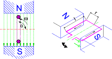
Generation of Single Phase e.m.f At the most basic level a simple electrical generator as shown in principle below provides a sinusoidal voltage output.
The e.m.f generated in one side on the loop is B.l.u. sin θ ..(Zero voltage results when
the side of the loop is moving parallel to the lines of magnetic flux and
voltage = B.l.u when the velocity (u) is normal to the lines of flux.) .
( ref Electromagnetic Induction ) e = 2.B.l.u.sin θ = 2.B.l.ω.r.sin θ = B.A.ω.sin θ = B.A.2.π.n.sin θ Note: A = area of covered by the loop = l.2.r Alternatively if E m =B.A.ω the instantaneous e.m.f. = e = E m sin θ = E m sin ω.t If the loop is replaced by a coil of N turns in series each having a area (2.r.l) = A then the maximum e.m.f.
generated in the coil = e = E m sin θ = B.A.2.π .n.N sin θ Average and R.M.S Values of sinusoidal These notes relate primarily to cyclic variations of a variable.
The principles also apply to
variables which are constantly changing over time.
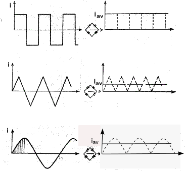
For the square wave pattern the average value of the full wave rectified form is i av = I m
In practical electrical engineering the average value is of little importance.
It is most important to consider the work that the electricity
can do either in heating or in mechanical work. This is generally related to the power
equivalent of the current W = I2 /R or V2 /R Consider one cycle of the square waveform as shown below. (two cycles actually shown)
Assuming the current is delivering energy by heating a 4 ohm resistor. The total energy delivered over a complete cycle = Energy = Σ i 2 R.t = [22.1 + 52.1 + -22.1 + -52.1].4 =58.4 =232 Joules The equivalent direct current to produce the same heating effect over a complete cycle = I. I 2 R.t= =232 Joules Therefore I = Sqrt (232 / R.t) = Sqrt [ 232 /( 4.4)] = 3.807 Amperes Note: The average full wave rectified value = (2.1+5*1)*2/4 = 3.5 Amperes I = 0,707.Im
The form factor for a sin wave is defined as the R.M.S value /Average value
The peak or crest value of a sine wave is defined as the maximum value /the R.M.S value
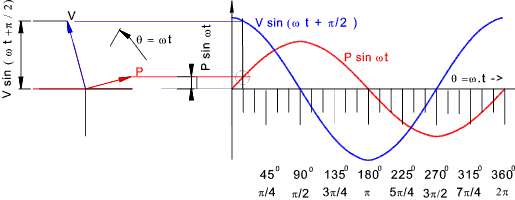
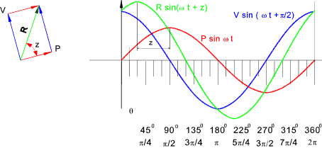
Vector Indication of AC values A sinusoidal variable can be shown as a plot of amplitude against time or θ = ω.t
The rotating vector on the left is assumed to be rotating at a constant angular
velocity ω Two sinusoidal alternating variables with different amplitudes and phases are shown together as below.
The two vectors can be added as shown below to obtain a resultant vector R.sin (ω t + z).
R and z are easily calculated as below as shown..
The methods of showing and adding sinusoidal variables is used when manipulating
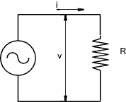
electrical currents currents flowing in circuits which include resistances, inductances, and capacitances Resistance In an AC Circuit Considering a AC circuit with a resistance of R.
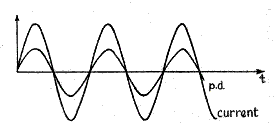
The ratio of the potential difference (V) across a resistor to the current (I) flowing through it it is a constant - This is Ohms law . This applies to steady currents and to varying currents. For the case of an Alternating current the potential difference and the current are in phase and the current at any time = i = v /R
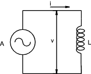
Inductances In an AC Circuit Inductance (L) is measured using the unit of 1 henry which is the inductance in when 1 volt is produced by a current changing at the rate of 1 ampere/second. If there is a steady DC voltage across an inductance it will result in no induced e.m.f and the only effect limiting the steady current will be the associated resistance.
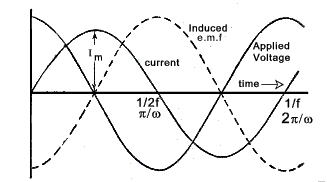
Consider a sine wave current through an inductance of L henries represented by the equation.. i = Im sin ωt. (t being the time in second after the current has passed through zero from negative to positive.) The instantaneous value of the induced e.m.f resulting from this changing current = The amplitude of the induced e.m.f = ω.L.Im and the resulting e.m.f sine wave effectively lags the current by ω /2 . The sine waves are shown below
Note: The frequency f = ω /(2.π) and the wavelength = 1/f = 2.π /ω Assuming there is no resistance all of the applied voltage is absorbed in neutralising the induced e.m.f . Therefore
The applied voltage leads the current by π /2 and the maximum applied voltage = ω.L.I m that is
The inductive reactance is expressed as ohms and is represented by the symbol X L.
Therefore I = V /X L = V /(2.π.f.L).
Unlike a resistance there is no energy absorbed in an inductance subject to a sine wave applied voltage.
Capacitances In an AC Circuit
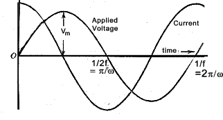
Referring to the curve below at time = 0 the rate of increase of applied voltage is such that
the current is at a maximum value.
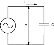
Note: The frequency f = ω /(2.π) and the wavelength = 1/f = 2.π /ω Considering sinusoidal voltage applied across a purely capacitive circuit the following relationships apply.
As the instantaneous value of the current is i = C.dv/dt then..
It is clear that the current leads the voltage by π /2 and the maximum value = ωC Vm
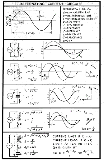
Summary of AC Circuit formula
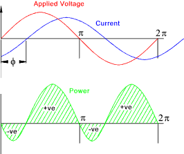
Power Factor Consider a conductor with applied AC voltage with an out of phase current. The curve below shows an applied voltage with a current which is lagging the voltage by φ.
The instantaneous voltage v = V m sin(ω.t ) Over a complete cycle the average value of cos (2ω - φ ) = 0. ......(it is varying sinusoidally )
It is clear that if the phase difference is +/- (π /2) a purely capacitive or inductive load then the
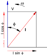
power from the alternator = 0. Power in watts = Voltamperes .power factor = V.I.cos φ For an alternative view on the topic consider an alternating voltage V with a current lagging by φ shown vectorially below..
The current can be resolved into two components I cos φin line with the voltage and I sinφ at right angles to the voltage. The power due to the first component is VI cosφ is the power or active component. The power due to the second component = V (I.sinφ) cos 900 = 0 this is the reactive or wattless component of the current Generation of Three Phase supplies Consider three loops each position 120o relative to each other rotating in a magnetic field as shown below
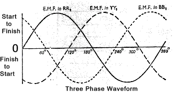
The loops are being rotated anti-clockwise and each loop is producing exactly the same
emf with the same amplitude and frequency but the loop Y Lags loop R by 1200
and the loop B lags loop Y by 1200. This is the same for the associated loop Y 1,
B 1, and R 1 . At any moment the e.m.f generated in the three loops are as follows
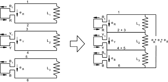
e R = E m sin ( θ ) Mesh /Delta Connection of Three Phase supplies The three phases can be shown as below as separate circuits with six conductors between the generator loops and the respective loads
This system results in six conductors and can be simplified to reduce the number of
conductors. Initially it is possible to replace conductors 2 and 3 with one conductor and conductors
4 and 5 with one conductor. It can also easily be proved that there is no
voltage difference between 6 and 1 allowing these also to be connected as one conductor and any stage in the cycle, as follows e R + e Y + e B = E m [sin ( θ ) +
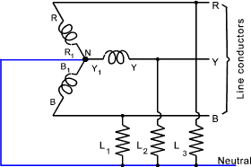
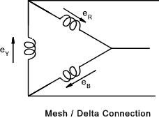
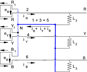
sin ( θ -1200 ) + sin ( θ -2400 ) ] This method of connecting the conductors in a three-phase system is called a Mesh or Delta connection and is generally shown as below Star Connection of Three Phase supplies If the three start conductors 1,3,and 5 connected as one conductor NM as shown (in blue) below then the current flow is as shown...Three phase motors can be connected to the line conductors R.Y and B while lights, heaters etc are usually connected between the line conductors and the neutral line as shown by (L 1,L 2 & L 3 )
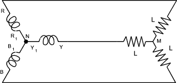
This conductor arrangement is normally shown as below
Ideally if the loads L 1, L 2 and L 3 are the same then the phase currents have the same peak value I m and differ in phase by 1200
i 1 = I m sin ( θ ) The resultant total current in the Neutral line = i 1 +i 2 +i 3 = I m[sin (θ) + sin ( θ -1200 ) + sin ( θ -2400 ] = I m. (0) = 0 Hence with balanced loads there is no load in the neutral line at any instant and the neutral line can be removed resulting in the three wire star system as shown below...
It can be proved that at every instant, for balanced loads the algebraic sum of the currents flowing in the three conductors is zero Transformers
A transformer is an electromagnetic device having two or more stationary coils coupled through a mutual magnetic flux.
Transformer are used to increase or decrease voltages. Tranformers are essential in the electrical power
transmission industry allowing power to be generated at one voltage and then stepped up to higher
voltages for long distance transmission. The voltages can then be stepped down for driving
motors and operating heaters and lamps.
In the UK for long distance power transmission the voltage is stepped up to 400/275 kV.
It is then progressively reduced to 11kV for transmission within urban areas. It is locally progressively
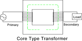
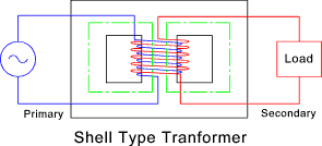
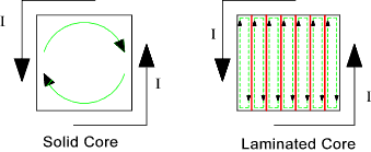
reduced to 380-415V (phase to phase -3 phase) 220-240 Volts (phase to nuetral - single phase) A transformer consists of an metal core of laminated sheets about 0,35mm thick insulated from
each other to reduce eddy current losses. The vertical parts as shown are called the limbs
and the horizontal parts are called the yokes. The two coils are wound on the limbs. One coil
is called the primary coil and the other is called the secondary coil.
An alternating voltage applied to the primary coil results in an alternating current which produces an alternating magnetic flux in the metal core. The current /flux level is just sufficient to induce an e.m.f that is practically equal and opposite to the applied voltage. The mean path of the alternating flux is indicated in the figure. Assuming all of the flux passes through the primary and the secondary winding,it induces the same e.m.f. in each turn of both coils. Hence if N1 and N2 are the number of turns in the primary and secondary coils respectively .
When the secondary winding is in open circuit its terminal voltage is the same as the induced e.m.f . The primary current is such that the induced e.m.f is equal and opposite to the applied alternating voltage. When a load is connected to the secondary winding a current flows. This secondary current induces a magnetic flux which tends to reduce the current flow (Lenz's Law). The induced flux tends to reduce the magnetic flux and the resulting back back e.m.f.in the primary windigs This changes the difference between the applied voltage and the back e.m.f.in the primary windings from (say 0,05% to 1%). As a result the primary current increases, by say 20 times the no-load current. The demagnetising ampere turns of the secondary winding are thus neutralised by the increase in the primary ampere turns.. As the initial no-load primary ampere-turns are very small it can be stated that Full load Ampere-Turns on (Primary) = Full load Ampere-Turns on (Secondary) In practice the above are all approximate Transformer Losses The energy wasted in a transformer can be divided into magnetic leakage
losses copper losses and iron losses.
The iron losses are hysteresis losses and eddy current losses. The hysterisis losses are described on webpage
Electromagnetism - Hysteresis Losses.
Motors
There are a number of methods of classifying AC motors |
Useful relevant Links
|
|
Electrics Index






 ..
..