Introduction
This webpage includes notes on methods of calculating radial deflections on
shafts transmitting torques and subject to lateral loads and moments which tend to bend the shaft.
The notes are provided to enable basic outline calculations to be carried out. For detailed design work
it is recommended that quality reference documents are used.
Online calculators are provided
which can also provide convenient methods of evaluating the deflections. One I have used is
Mitcalc. com ( see link below).
Various methods are available for calculating the deflections of a shaft . Many of these are described
on pages indexed at webpage Beam index. The calculation
of beam deflections can be simplified by using the principle of superposition . The deflections
resulting from seperate loads in the same plane , or different planes, can be seperately calculated and
then combined arithmetically or vectorial to arrive at the deflections of the combined loading scenario.
It should be noted that, in general, there is only a need to determine the radial/angular deflection at the
location of a bearing , gear, spline, coupling etc. It is not , generally, necessary to determine the deflection
in the mid point of a shaft, in space, assuming that the deflection is not excessive.
A first step is always to determine the forces and moments resulting from gears, belts, weight of components etc and
calculate the bearing reactions. It is generally simpler to calculate these with reference to the horizontal
and the vertical planes eg. a force at an angle to the vertical has a component in the horizontal plane and one in the
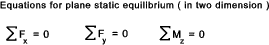
vertical plane. The reactions are generally calculated using the principles of static equilibrium.
Examples of using this principle are found on web page Shear Bending moment diagrams.
Shafts of same diameter
It is often sufficient to calculate the deflections based on the shaft being one diameter. This
clearly results in a conservative value if the diameter used is the minimum diameter.
Shafts of with many diameters
For more complicated shafts with more than one diameter various methods are available including the
Area Moments method ref. Beam Theory
and Energy methods (Castigliano's method) . ref. .Energy Methods However it is often easier to use
numerical integration to obtain shaft deflections which are reasonably accurate. This basis for this method is the differential equation below
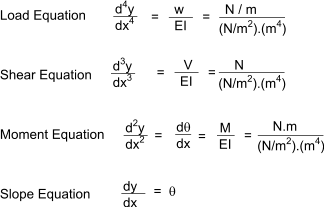
.
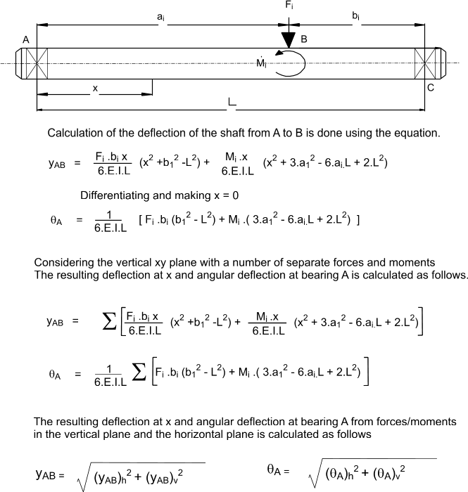
The simple basis of this method is that the change in slope between two points Δθ = Δx.(M/EI) .... Δx being the
distance betwen the points. The resulting change in deflection is clearly Δθ.Δx.
If this simple rule is applied along the shaft the cummulative slope relative to the initial slope can be evaluated and also the progressive change in deflection.
The smaller the x increments :the more accurate the calculation. The angles
and deflection are all relative to the tangent of the left hand point. If the origin is a bearing then it is clear that
the second bearing is at the same radial position as the first bearing. By simply dividing the calculated overall
deflection between the bearings by the centre distance an integration factor (K) results which can be used to convert the relative deflections
to absolute by subtracting K.Δ.x from each of the deflection values.
The method is based on one provided in the book "Machine Design: Theory and Practice..
by A.D Deutshman, W.E.Michels, C.E.Wilson, (McMillan Publishing Co Inc)"
A version of the spreadsheet below has be created with the excelcalc.com repository which enables convenient
access to the method of calculating deflections of stepped shafts ref ExcelCalcs.com calculation Shaft Deflections
The first step is to evaluate all forces and reactions in the shaft and identify
points along the shaft at each force and reaction and change of section. It is also more accurate if long sections of constant diameter
with no loads are divided into smaller intervals with associated points.
This method is illustrated using a shaft example below (vertical and horizontal planes ).
|
Note:I have completed this example using excel. It takes about 20 minutes to set up the spreadsheet
for calculating the deflections in the vertical plane.
The table for the deflections in the horizontal
plane takes about a minute because the whole table can be cut and pasted and only the forces need to be changed. Further shaft calculations are then
relatively easy because the existing worksheet can easily by used as a template. I have checked the
values against the results from using Mitcalc.com (shafts) and they are reasonably consistent(within 5%).
For this example I have not included the weight of the shaft. The effect of this on the worst case
deflection between the bearings is about 0,04mm. (I used Mitcalc.com to check this ).
This clearly shows that for many applications it is not necessary to consider the deflection due to
self weight. For cases where the vertical forces tend the bow the shaft
upwards the self weight actually reduces the deflection. - The example below is very much a case where the
self weight contributes to the deflection and is still very small compared to the total deflection. The weights can be reasonably accurately covered by adding the
force resulting from the weight of each section to be added at a point midway along the section length. |
Shaft Details
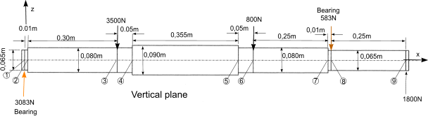
Material Steel
E 210.10^9 Pa ( N/m2 )
Dia shaft at points 1-2/7-8; 0,065m (65mm) ..I = 8,762.10-7 m4..IE = 1,84.105.Nm2
Dia shaft at points 2-4/5,7; 0,080m (80mm) ..I = 2,01.10-6 m4..IE = 4,22.105.Nm2
Dia shaft at points 4-5; 0,095m (95mm) ..I = 8,998.10-6 m4..IE = 8,39.105.Nm2
Bearing centre distance = 1,025m (1025mm ). This is used to calculate the total integration constant
The following step by step approach is used to complete this procedure
1) Construct a table with the columns as shown. Calculate the bearing forces.
Calculate the valuesof EI for each section. Calculate the bearing centre distance.
2) Divide shaft into intervals with designated points at each force and change of section. If more accuracy
is required long then sections of the same diameter can also be divided and allocated point references.
3) List the point number on each alternate row. (space between each point row ).
4) List the forces against the relevant point in column 2. List the distances between the points in column 5. List the EI values in column 6.
5) Calculate the shear force( V)at each point by summing the forces in the preceding rows of column 2 enter (V) in column 3 against the relevant point .
6) Calculate the Bending moment (M = V.x) resulting from the shear force(V) and the distance to the preceding point (x).
Add this value to the previous value of M in the point row above and enter this new value of M in column 5 in the current point row.
7) Complicated bit.Calculate M/EI values for each point. Two values are required for each point, one entered in column 7 in the point row and the second in the row below.
The first value is M in the point row divided EI in the next row. The second value is M in the next point row divided by the same EI value.
8) Calculate the average of each pair of M/EI values ((Sum of values /2) and enter in column 8 in the row below the point row.
9) Calculate slope (relative to that at point 1) at each point. = slope at previous point + M/EIav. x . Enter this value to column 9 value
10) Calculate the average relative slope between each point (slope x + slope x+1)/2. Enter this in column 10 in the row between the points.
11) Calculate shaft deflection resulting from the average slope by multiplying the slope by the x value in the following row .
This is entered in column 11 in the same row as the average slope
12) Total all the deflection increments between the bearing centres (between rows 1 and 8 in example below).
Divide this value by -(bearing centre distance). This is the integration constant. (K)
Note: The slopes calculated have all been relative to the slope at point 1. They are relative not
absolute values. The resulting calculated deflections are also relative to the tangent of the shaft
at point 1 - they are not absolute values. The total deflection between the bearings is zero and
thus the integration constant is the proportional error away from the correct value (error /m) . This is used
to correct all of the intermediate values as follows
13) Multiply the total integration constant (K) by the x values between points. Add this relative
integration constant value in column 12 in the same row as the deflection increment.
14)The corrected deflection at each point is the product of the relative integration constant
and the calculated deflection increment in the preceding row. Enter this in the point row in column 13.
To this add the corrected deflection of the previous point to make up a running total.
The slopes calculated are also relative to the tangent at point 1. To arrive at the absolute
slope /angle at any point simply add the angle correction value. θ c = (- tan-1 ((K) ).
| 1 | 2 | 3 | 4 |
5 | 6 | 7 |
8 | 9 | 10 | 11 |
12 | 13 |
| Point on shaft | Force
Reaction |
Shear at
preceding
point (V) |
Dist.(x) | B.M
(M) |
Flexural rigidity |
- |
Average
of (1000.M/EI) |
Slope
relative to
Point 1 |
Average relative.
slope |
Deflection
increase |
Integration
constant |
Deflection |
| F |
V |
Lx |
∑(V.Lx) |
EI |
1000.M/EI |
(100M/EI)av |
θ =
∑Lx(M/EI)av |
θav |
δrel=
θav.Lx |
K |
δ |
| N |
N |
m |
Nm |
N.m2 |
mm-1 |
mm-1 |
m.rad |
m.rad |
mm |
mm |
mm |
| 1 |
3083.41 |
|
|
|
|
0 |
|
0 |
|
|
|
0 |
| |
|
|
|
|
184011 |
0.168 |
0.08 |
|
0.001 |
0 |
-0.006 |
|
| 2 |
|
3083.41 |
0.01 |
30.83 |
|
0.073 |
|
0.001 |
|
|
|
-0.006 |
| |
|
|
|
|
422230 |
2.264 |
1.17 |
|
0.177 |
0.053 |
-0.186 |
|
| 3 |
-3500 |
3083.41 |
0.3 |
955.85 |
|
2.264 |
|
0.352 |
|
|
|
-0.139 |
| |
|
|
|
|
422230 |
2.214 |
2.24 |
|
0.408 |
0.02 |
-0.031 |
|
| 4 |
|
-416.59 |
0.05 |
935.02 |
|
1.114 |
|
0.464 |
|
|
|
-0.15 |
| |
|
|
|
|
839622 |
0.937 |
1.03 |
|
0.647 |
0.23 |
-0.22 |
|
| 5 |
|
-416.59 |
0.355 |
787.13 |
|
1.864 |
|
0.83 |
|
|
|
-0.14 |
| |
|
|
|
|
422230 |
1.815 |
1.84 |
|
0.876 |
0.044 |
-0.031 |
|
| 6 |
-800 |
-416.59 |
0.05 |
766.3 |
|
1.815 |
|
0.922 |
|
|
|
-0.127 |
| |
|
|
|
|
422230 |
1.095 |
1.46 |
|
1.105 |
0.276 |
-0.155 |
|
| 7 |
|
-1216.59 |
0.25 |
462.15 |
|
2.512 |
|
1.287 |
|
|
|
-0.006 |
| |
|
|
|
|
184011 |
2.445 |
2.48 |
|
1.299 |
0.013 |
-0.006 |
|
| 8 |
-583.41 |
-1216.59 |
0.01 |
449.98 |
|
2.445 |
|
1.31 |
|
|
|
0.001 |
| |
|
|
|
|
184011 |
0 |
1.22 |
|
1.47 |
0.37 |
-0.155 |
|
| 9 |
1800 |
-1800 |
0.25 |
-0.02 |
|
|
|
1.62 |
|
|
|
0.216 |
| |
|
|
|
|
|
|
|
Total Integration Constant; |
K = -0,6205mm |
| |
|
|
|
|
|
|
|
Angle integration Constant; |
θ c = -0,62 mrad |
To calculate the shaft angle,in the vertical planes, at the bearing centres Points 1 and 8. Simply add θ c to
the tabled angles at these points.
At point 1 shaft angle 0+(-0,620mrads) =-0,620mrads ( -0,0355 deg.)
At Point 8 the shaft angle = 1,31mrads+(-0,620mrads)=0,69 mrads ( 0,039 deg.)
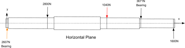
Deflections in Horizontal plane
The same method is applicable for obtaining the deflections in the horizontal plane
| 1 | 2 | 3 | 4 |
5 | 6 | 7 |
8 | 9 | 10 | 11 |
12 | 13 |
| Point on shaft | Force
Reaction |
Shear at
preceding
point (V) |
Dist.(x) | B.M
(M) |
Flexural rigidity |
- |
Average
of (1000.M/EI) |
Slope
relative to
Point 1 |
Average relative.
slope |
Deflection
increase |
Integration
constant |
Deflection |
| F |
V |
Lx |
∑(V.Lx) |
EI |
1000.M/EI |
(100M/EI)av |
θ =
∑Lx(M/EI)av |
θav |
δrel=
θav.Lx |
K |
δ |
| N |
N |
m |
Nm |
N.m2 |
mm-1 |
mm-1 |
m.rad |
m.rad |
mm |
mm |
mm |
| 1 |
2607,22 |
|
|
|
|
0 |
|
0 |
|
|
|
0 |
| |
|
|
|
|
184011 |
0,142 |
0,071 |
|
0,001 |
0 |
-0,005 |
|
| 2 |
|
2607,22 |
0,01 |
26,07 |
|
0,062 |
|
0,001 |
|
|
|
-0,005 |
| |
|
|
|
|
422230 |
1,914 |
0,988 |
|
0,149 |
0,045 |
-0,161 |
|
| 3 |
-2800 |
2607,22 |
0,3 |
808,24 |
|
1,914 |
|
0,297 |
|
|
|
-0,121 |
| |
|
|
|
|
422230 |
1,891 |
1,903 |
|
0,345 |
0,017 |
-0,027 |
|
| 4 |
|
-192,78 |
0,05 |
798,6 |
|
0,951 |
|
0,392 |
|
|
|
-0,131 |
| |
|
|
|
|
839622 |
0,87 |
0,911 |
|
0,554 |
0,197 |
-0,191 |
|
| 5 |
|
-192,78 |
0,355 |
730,16 |
|
1,729 |
|
0,715 |
|
|
|
-0,125 |
| |
|
|
|
|
422230 |
1,706 |
1,718 |
|
0,758 |
0,038 |
-0,027 |
|
| 6 |
-1040 |
-192,78 |
0,05 |
720,52 |
|
1,706 |
|
0,801 |
|
|
|
-0,114 |
| |
|
|
|
|
422230 |
0,977 |
1,342 |
|
0,969 |
0,242 |
-0,134 |
|
| 7 |
|
-1232,78 |
0,25 |
412,33 |
|
2,241 |
|
1,137 |
|
|
|
-0,006 |
| |
|
|
|
|
184011 |
2,174 |
2,208 |
|
1,149 |
0,011 |
-0,005 |
|
| 8 |
-367,22 |
-1232,78 |
0,01 |
400 |
|
2,174 |
|
1,16 |
|
|
|
0 |
| |
|
|
|
|
184011 |
0 |
1,09 |
|
1,3 |
0,33 |
-0,134 |
|
| 9 |
1600 |
-1600 |
0,25 |
0 |
|
|
|
1,43 |
|
|
|
0,196 |
| |
|
|
|
|
|
|
|
Total Integration Constant; |
K = -0,537 |
| |
|
|
|
|
|
|
|
Angle integration Constant; |
θ c =-0,537 mrad |
To calculate the shaft angle,in thehorizontal planes, at the bearing centres Points 1 and 8.
Simply add θ c to the tabled angles at these points.
At point 1 shaft angle 0+(-0,537 mrads) =-0,463mrads (0,031 deg).
At Point 8 the shaft angle = (1,16mrad+(-0,537mrad) =0,623 mrads (0,036 deg.)
Calculating shaft deflection
The numerical methods above enable calculation of the deflection of the shaft in the horizontal and vertical planes. To obtain the total
resultant deflection and the angle of the resultant deflection . The following calculations are completed
δR = Sqrt (δH2 + δV 2 )
Angle of resultant from horizontal = tan -1 (δH / δH )
Example..based on shaft above..
The total deflection at point 3 = Sqrt[ (-0.139)2 + (-0.121)2 ] =0,184mm
|