Introduction
A most important factor is machine design, and structural design is the
rigid fastening together of different components..This should include the following considerations..
- Assembly
- Accuracy of positioning
- Ability to Hold components rigidly together against all forces
- Requirement to separate components
- Retention of fastening over time
|
There are many methods of fastening items together including
- Bolting
- Rivetting
- Pins
- Keys
- Welding/Soldering/Brazing
- Bonding
- Velcro
- Magnetism
|
These notes relate primarily to the bolted joint. The bolted joint
is a very popular method of fastening components together. The prime reason
for selecting bolts as opposed to welding, or rivets is that the connection
can be easily released allowing disassembly, maintenance and/or inspection..
The bolts /screws are generally used in groups to fasten plates together.
A bolt is a screwed fastener with a head, designed to be used with a nut. A screw
is a fastener designed to be used with a formed female thread in one of the components being attached.
These notes generally relate to bolts and nuts and hex headed screws..
Bolt loading
A bolt can be loaded in one of three ways
- Tension
- Shear
- Combined Shear and Tension
|
Note: Conditions where bending loads are imposed on the bolt e.g. non-parallel bolting surfaces, should be avoided.
A bolt is primarily designed to withstand tensile loading while clamping components together.
Ideally the bolt should only be loaded in tension. Any forces tending to slide the
clamped components laterally should be withstood by separate means..
Holes for bolts are generally clearance holes and the best design of bolt
is one with a reduced shank diameter (waisted shanks).
Joints in shear depending on the bolts to withstand the shear load are not really
rigid. Significant relative sideways movement must take place before the bolt shank
can take any shear load (hole clearance). It is also likely that in the case of components
attached by a number of bolts that one bolt would be loaded first and this bolt
would have to yield before the other bolts take their share of the shear load....
Bolts taking significant tensile and shear load need to be engineered to withstand the combined stress..
In structural engineering the codes identify the use of High Strength
Friction Grip Bolts (Ref BS 4604 Pts 1-2:1970).
The bolts are tightened to a specified minimum shank tension so that transverse
loads are transferred across the joint by friction between the plates rather
than by shear across the bolt shank.
In mechanical engineering / machine engineering, items are often accurately located
using dowels /locating pins. When installed these dowels /locating pins should be engineered to withstand
any traverse loads.
A recent innovation is to provide dowel bushings. These are used
in conjunction with bolts which pass through the inside of the bushing after
it has been installed. Separate holes for locating pins are eliminated.
The hardened bushings absorb shear loads, isolating the bolts from these forces.
If the choice is made that bolts/screws are to take shear load the joint should be
arranged that the threaded portion of the bolt/screw shank is not taking the shear.
|
The notes on this page relate to the mechanical engineering industry.. In the aerospace industry
joints are often designed to specifically load the bolts in shear.
The screws and bolts used are high specification close toleranced items and the holes
are also machined to close tolerances. The bolted lap joints are generally
used for critical assemblies and joints designed with bolts loaded in tension are
avoided.???? |
Strength of Bolts in Shear
Important Note:
The calculations below are based on the unrealistic assumption that there is no friction
forces between the plates which are clamped by the bolts. The calculations are
therefore conservative (safe)..
Strength of Bolts withstanding direct shear loading
For bolts joints loaded in shear - three stress areas result-
- The bolts are loaded in shear..Depending on the joint design the bolt can be in single or double shear...
- The bolt interface with the hole is compressively loaded. ( Crushing )
- If the hole is near to the edge of the plate the plate is subject to shear loading
|
Single Shear..
Shear Stress = 4 . F / π. d 2
Compressive Stress = F / (d . t)
Plate Shear Stress = F / (2.c.t)
Double Shear ..
Shear Stress = 2 . F / π. d 2
Compressive Stress = F / (d . t)
Plate Shear Stress = F / (2.c.t)
The stresses are adjusted based on the number of bolts / screws used for the joint..
Strength of bolts withstanding torsion generated shear loading
Consider a bracket taking an offset load F (N) at a radius R (m). The bracket is secure using a number
of bolts each with a Area A(m2 ). The bolts are located around a centroid position
each with a radius from the centroid of rn(m) and a horizontal/vertical position relative to the centroid
of hn /vn (m) . ( bolt is designated by the subscript "n". )
Location of Centroid...
The location of the centroid of the bolts can often be determined by inspection as in figure above.
If the bolts are not arranged around a convenient centre then the centroid is
determined by ..
x position = sum of the moments of area of all the holes about a fixed horizontal position divided by the total hole area
y position = sum of the moments of area of all the holes about a fixed vertical position divided by the total hole area
|
The offset load is equivalent to a vertical force (F) + moment (F. R) at the centroid of the bolts...
Each bolt is withstands a vertical shear force Fnv = F / No of Bolts.
Each bolt also withstands a shear load Fnm = F.R. rn / (r12 + r22...rn2)
The total horizontal force on each bolt Fth= Fnm . vn / Sqrt(hn2 + vn2 )
The total vertical force on each bolt Ftv= Fnv + Fnm . hn / Sqrt(hn2 + vn2 )
The total shear load on each bolt Ft= Sqrt (Fth2 + Ftv2)
The resulting bolt shear stress τ t = Ft /A
The shear stress in each bolt is calculated to ensure the design
is safe..
Strength of bolt joints withstanding bending forces
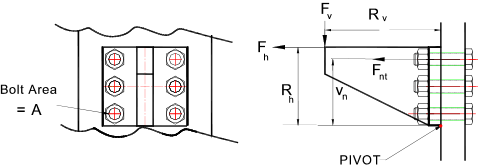
Each Bolt withstands a shear Force Fs = Fv / (Number of bolts)
The resulting shear bolt stress τ n = Fs /A
Note: Each bolt is assumed to withstand the same shear force.
If there are x bolts( numbered n = 1 to x). Then the tensile force withstood be each bolt is designated Fnt i.e F1t,F2t, F3t....Fxt
A selected bolt (n) withstands a tensile force of Fnt =
( Fv. Rv + Fh. Rh) . Vn / (V12 +
V22....Vx2 )
The resulting tensile bolt stress sn = Fnt /A
Maximum principals stresses in the bolt resulting from combined loading
The notes on this page Assuming all stresses developed only as a result of bracket loading i.e
zero preload and zero residual bolt torque...
Maximum principal tensile stress in the bolt
Maximum principal compressive stress in the bolt
Maximum shear stress in the bolt
Failure criteria: Refer to page Failure Modes
The notes on this page In order to estimate the design factors of safety it is necessary to consider the failure modes.
The preferred failure criteria for ductile metals is the "Shear Strain Energy Theory"
(Von Mises-Hencky theory).
For a stress regime associated with a bolt i.e pure tensile stress sx
combined with shear stress τ xy. The Factor of safety relative
to the material tensile strength Sy..is calculated as follows
Factor of Safety = Sy /
( sx2 +
3 .τ xy2 ) 1/2
Preloaded Bolts : Refer to page Preloading
These stresses do not include for the stresses developed in preloading the bolts. The residual
shear stress from bolt tightening should also considered (added). The actual tensile preload force
should be considered following the principles identified on the pages addressing this topic
|