| |
| These Pages include various standards. To confirm the status of any standard, identify the replacement standard if it is obsolete and/or purchase the standard please use. It is also possible to become a BSI member and obtain copies of the Standards at much reduced prices. |
Structural Design
Introduction..... Formwork..... Standards..... Symbols..... Properties..... Methodology..... Design working life..... Resistance..... Actions..... Classification..... Frames..... Connections.....
The building structures pages have been added over the six months to Dec. 2012. They are very much work-in-progress and I will be updating them on a regular basis over the next six months.
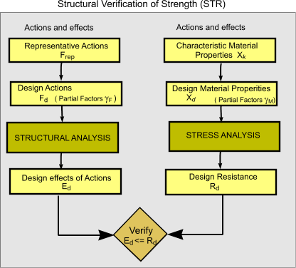
| Introduction This section includes outline notes on the design of structures. The notes are general in nature and are included to provide understanding of principles involved. It does not provide sufficient information to allow detailed design to be completed. For detail design of structures the relevant standards should be used and also reputable reference documents. In fact for all but the most simplest structures, design generally requires use of computer systems. For free software programme "Framework" which allows design of simple structures even in accordance with the relevant Eurocoodes ref Mechanical programs. The information on this page is, as of June 2012 very limited, however links are provided in the text and at the foot of the page which include very detailed information sufficient for detail design. This page also includes a list of the current relevant standards. This website includes notes on the elastic design of beams, columns and frames in the pages linked below.
Relevant Standards Eurocode 3: Design of Steel Structures
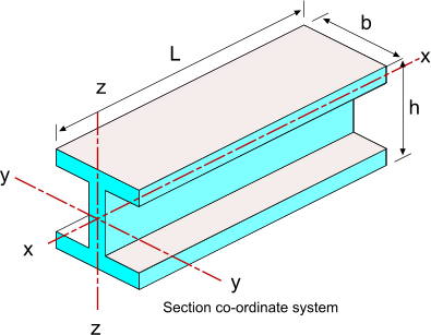
Symbols
Material Properties for Steel Structures The material properties are found in the relevant steel standards e.g. BS ISO 10025. The following relationships apply. fy = ReH BS EN 1993 -1 clause 3.2.2 identifies the recommended ductility requirements for structural steel in terms of the ratio of fu / fy,the elongation at failure, and the ultimate strain fu / fy >= 1,10 BS EN 1993 -1 clause 3.2.6 identifies the recommended design values for structural steel coefficient as follows Modulus of elasticity E = 210 000 N/mm2 Design methodology as required by BS EN 1993
Design Life The intended design life of the construction should be identified at the initial stage of the design process table of design lives of buildings in accordance with BS EN 1990 clause 2,3
Design Resistance Notes on the resistance to of a structure are provided on webpage Eurocodes Intro A variation on the equations as applicable to steel structures provided below.
Xk = characteric value of material property
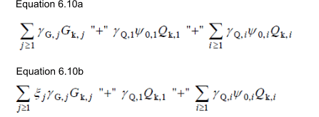
Notes on Resistance are found on webpage introduction to eurocodes. Eurocodes Introduction Design Actions For steel structures the design effect of actions is ( Ed ) is defined on webpage Eurocodes Intro. The general equation for the Effect of actions should be
The part of the equation inside the brackets represents the combination of permanent and variable actions
Notes on Actions (imposed forces) are found on webpage introduction to eurocodes. Eurocodes Introduction Classifying Structural elements The simplest classifications of structures is based on the method of analysis. Structures can be either statically determinate
or statically indeterminate. Statically determinate structures can be analysed using the principles of simple statics and statically indeterminate structures
can not.
Frames definition A frame is part of, or all of a structure , comprising of an
assembly of directly connected structural elements, designed to act together to resist
load. This relates to moment resisting frames and triangulated frames and
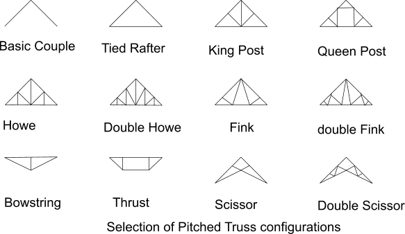
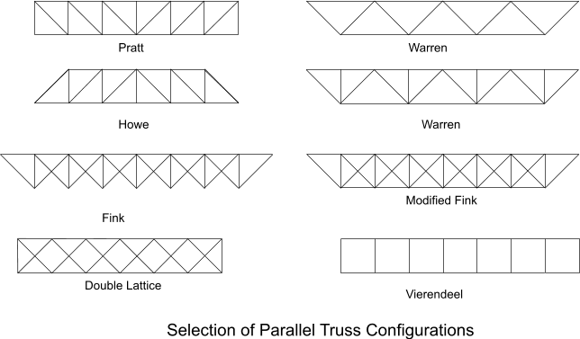
covers both plane frames and three-dimensional frames. Frames types Trusses A truss is a structure comprising one or more triangular units constructed with straight members whose ends are connected at joints referred to as nodes. External forces and reactions to those forces are considered to act only at the nodes and result in forces in the members which are either tensile (in a tie member) or compressive forces (In a strut member. All of the nodes in a truss are assumed to be pin joints which do not transmit moments. Trusses are easily separated into two groups : pitched trusses as used for building roofs and parallel trusses which are often used for spanning e.g bridges. The figures below illustrate ,very crudely, a selection of truss designs. These are shown as planar constructions . The designs are also relevant to 3 D constructions " Space Frames". Selection of Pitched Trusses
Selection of Parallel Trusses
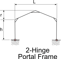
Portal Frames Many single story buildings are constructed from basic portal frames. Portal frames are generally two
dimensional rigid frames based on support columns and traversing beams. The frames have the basic characteristics of a
rigid joint between column and beam. Portal frames are generally constructed from Steel or reinforced concrete but timber
is also used.
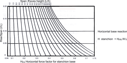
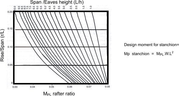
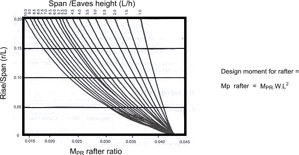
The forces involved in three hinged portal frame can generally be easily resolved using statics. The problem is then broken down to determination of the shear forces and the bending moments for the two individual beams making up the portal frame. Two hinged and hingeless portal frames are classified as statically indeterminate structures and conditions other than statics conditions have to be used to calculate the end reactions and moments. Consider a two hinge portal frame as shown below. Plastic hinges are formed in the eaves and near the apex. A very preliminary method of estimating the horizontal base loads and the design moments in the rafters and stanchions involves using the graphs as shown below.
The load W = the vertical rafter load per metre run The Horizontal base reaction can be obtained using the graph below
The design moment for the stanchion be obtained using the graph below
The design moment for the rafter be obtained using the graph below
Connection types Connections between structural elements is one of the most important areas of design structural steelwork. There are three principle types of connection . 1) Simple connections transmit negligible bending moments across the joint . This joint allow the
beams to rotate relative to each other . They are effectively pin joints.
|
Useful relevant Links
|
|
