These Pages include various standards. To confirm the status of any standard, identify the replacement standard if it is obsolete and/or purchase the standard please use. It is also possible to become a BSI member and obtain copies of the Standards at much reduced prices.

Timber Example Calculation to Eurocode 5

Example description.... Actions.... Timber Properties.... Bending.... Deflections.... Vibration.... Lateral Buckling.... Shear.... Bearing....

The building structures pages have been added the six months to Dec. 2012.     They are very much work-in-progress and I will be updating them on a regular basis over the next six months.

Example Description

To Design the timber floor joists for a domestic dwelling using timber of strength clss C16 based on the following data

Floor width , b = 3,6m and floor span L is 3,4m
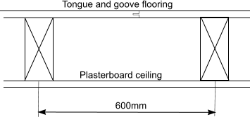
Joists are spaced at 600 mm centres
Flooring is tongue and groove of thickness 21mm and self weight of 0,1 kN /m2
Ceiling is plasterboard with a self weight of 0,2 kN/m2
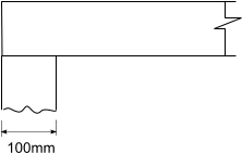
Bearing length = 100mm
Area of floor supported by each joist = Joint pitch . floor span A = 0,6  .  3,4 = 2,04 m2


Design Actions

Specific permanent action, gk
Tongue & grove boarding = 0.10 kN /m2
Ceiling = 0.20 kN /m2
Joists (say) = 0.10 kN /m2....
{ Each m2 includes about 2m of joist (assume 63mm x 200 mm with a csa of 12,6 mm2 ) this has a volume of about 25,2m-3m3 which at an average density of 370 kg/m3 weighs approx 9 kg.
The specific weight of the joists per m2 is therefore about 0,093kN/m2 }

Total characteristic permanent action = Gk 0,1  +  0,2  +  0,1  =   0,4 kN /m2

Specific variable action, qk
Imposed floor load for domestic dwelling (Eur. Intro _Imposed loads) is 2,0 kN /m-2

Design Load on the joists is

Fd = γG.Gk + γQ.Qk = γG.gk . A + γQ.qk. A
= 1,3  .  0,4  .  2,04  +   1,5  . 2,0   .  2.04   =  7,181 kN


Characteristic Properties of timber of class C16. ( N/mm2 )

Bending strength
fm,k
Compression strength
(perp to grain)
f,c,90,k
Shear strength
(paral to grain)
fv,k
Modulus of Elasticity. (Mean)
E0,mean
Modulus of Shear. (Mean)
G0,mean
16 N/mm2 4,6 N/mm2 1,8 N/mm2 8000 N/mm2 500 N/mm2


Bending

Assuming that the average moisture content of the timber joists does not exceed 20 per cent during the life of the structure, design the joists for service class 2. Service Class
Also as the joists are required to carry permanent and variable (imposed) actions, the critical load duration class is �medium-term� . Design strength values
Therefore kmod = 0,8 and γGM (for ultimate limit states) = 1,3 Design Strength Values
As the joists form part of a load sharing system the design strengths can be multiplied by a load sharing factor, ksys = 1,1 Design Strength Values


As the (assumed) beam is in bending and is over 150mm depth a value of kh = 1,0 is used

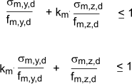
If members are not to fail in bending, the following conditions should be satisfied:

It is clear from   
Sawn timber geometry
A 63 mm � 200 mm joist (as assumed initially ) would be suitable
Wy = 420 � 103 mm3, Iy = 42 � 106 mm4, A = 12.6 � 103 mm2.


Deflections

Note simple equation used in this section are obtained from the following pages
Stress and strain
Shear stress

Instantaneous deflection due to permanent actions uinstG

The Partial factor γM for serviceability limit states = 1,0
Also the factored permanent load G = γG. Gk = 1,0 x 0,40 = 4,0kN/m2 .

The factored permanent load per joist Fd,G =

Fd,G = total load x joint spacing x span length = 0,4 x 0,6 x 3,4 = 0,82 kN

The instantaneos deflection due to permanent actions uinstG results from

uinstG = bending deflection + shear deflection.

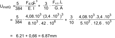
The instantaneous deflection due to variable actions uinstQ results from
The Partial factor γM for serviceability limit states = 1,0
Also the factored permanent load Q = γQ. Qk = 1,0 x 2,0 = 2,00 kN/m2 .

The factored permanent load per joist Fd,Q =

Fd,Q = total load x joint spacing x span length = 2,0 x 0,6 x 3,4 = 4,08 kN

Final deflection due to permanent actions reference... Deflections
For solid timber members subject to class 2 loading Kdef = 0,8 .    the final deflection due to permanent actions ufin,G is given by

ufin,G = uinst,G ( 1+ kdef) = 1,13 *1,8 = 2,034mm

Final deflection due to variable actions reference ...Deflections, reference Factor values
For solid timber members subject to class 2 loading Kdef = 0,8 . and for the variable action factor ψ2 = 0,3     the final deflection due to permanent actions ufin,Q is given by

ufin,Q = uinst,Q ( 1+ ψ2 . kdef) = 6.87 * (1 + (0,3.),8) = 8,51mm


Checking the final deflection

ufin = ufin,G + ufin,Q
= 2,034 + 8,51 = 10,544 mm
The permissible final deflections assuming the floor supports brittle finishes wfin =
wfin= 1/250 .span = (1/250).3400mm = 13,6mm
13,6mm > 10,544mm ..therefore deflection is acceptable.


Vibration

Assuming that f1 > 8 Hz it is necessary to check that

W/F         a            and        ν    b(f1.ζ -1 )

kstrut = 1,0
(EI)b = 8 .103 .(1000.213 / 12) = 6,18 .109 Nmm2 /m
Joist spacing s = 600 mm

Hence kdist =

Hence kdist = kstrut[0,38 -0,08 ln[14(EI)b/s4 ]         0,30
= 1,0.[0,38 -0,08 ln[14 . 6,18 . 109/6004 ] = 0,33
Leq = 3400mm
kamp = 1,05
(EI)joist = 8 .103 .(63.2003 / 12) = 3,36 .1011 Nmm2 /m

Therefore the maximum deflection caused by a concentrated static force F = 1,0, w, is


Check impulse velocity

Floor width, b = 3.4 m and floor span, l = 3.6 m.
Iy is the second moment of area of the joist (ignore tongue and groove boarding unless a specific shear calculation at the interface of joist and board is made):


Iy = 42 . 106 mm4 = 42 . 10-6 m4

E0,mean = 8 000 N / mm2 = 8 . 109 N / m2

(EI)L = E0,meanIy / joist spacing

= 8 . 109. 42 . 10-6 / 0,6 = 5,6 . 105 Nm2 /m

Mass due to permanent actions per unit area, m, is

m = permanent action / gravitational constant
= 0,40 � 103 / 9.81 = 40,8 kg /m2

The fundamental frequency of vibration, f1, is

The number of first order modes n40 is

The unit input velocity is

Assume the damping coefficient ξ = 0,002 form since a ( = 0,82mm) < 1 is given by

b = 180 -60.a = 180 - 60 . 0,82 = 131

Hence Permissible floor velocity =


Lateral Buckling

It is not necessary to check for lateral buckling because the beams are all supported along their length by the upper tongue and groove boards.


Shear

Reference... Shear


The design shear strength is

The maximum shear force is

Design shear stress at the neutral axis is


Bearing


reference Compression

The bearing design force is

F90,d = Fd/2 = 7.181 . 103 /2 = 3,59 . 103 N


The design bearing stress

Assuming that the floor joists are supported on 100m wide wallls as shown above the bearing stress resulting is calculated by

The design bearing strength

The design compressive strength perpendiculr to the grain fc,90,d is calculated as

a = 0 , L1 = 0 Therefore kc,90 = 1


Useful relevant Links
  1. Introduction to Structural Timber design to The Eurocodes..Very important document to latest codes :75 page document
  2. Strength Graded Timber Mark..Download showing identification to be shown on strength graded timber
  3. Wood Handbook -- Wood as an Engineering Material..Downloads ..Comprehensive Document (American ) Excellent
  4. Canadian Wood Council ..Excellent site on Wood Engineering - my words
  5. Timber Trade Federation ..The Timber Trade Federation is the official voice of the UK timber trade.
  6. In situ strength grade..Notes on visual strength grading of timber
  7. BSW Timber..Large UK Sawmill homepage