Electrics Index Direct Current
Introduction..... Nomenclature..... DC Generators..... DC Electric Motors.... Cells , batteries , accumulators.... Rectifiers.... Resistance....
|
Introduction
This page includes notes on direct current devices including generators, batteries, motors,
rectifers, resistances etc.
Nomenclature
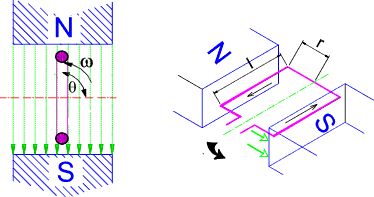
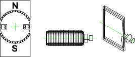
B = flux density (Teslas = webers/m2) DC Generators Consider a single rectangular coil of wire rotating in an magnetic field as shown below. The rotating coil is called the armature.
The coil is rotating at a angular velocity of ω.
The coil comprises two conductors each one has a length l.
The coil has a radius r. Em = Blu = Blωr As the coil rotates the total instantaneous e.m.f. generated in the coil (2 conductors) is given by the equation e = 2Blu.sin θ = 2Blωr sin θ = BAω sin θ Note The area of the coil A = 2lr In practice there are generally a number of conductors connected in
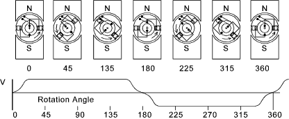
series in the slots on the armature. Emax = 2Blnu =2Bln.ωr ..... and..... e = 2Blnu.sin θ = 2Bln.ωr.sin θ If N is the number of turns (N =n/2) then e = 2BNlωr sin θ = BAω sin θ The figure below illustrates the armature voltage resulting from the progressive (ACW) rotation of the armature coil in a fixed magnetic field
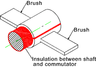
As can be seen the e.m.f induced changed direction on each half turn. To generate an e.m.f which does not change direction the brush contacts have to be reversed each time the coil rotates through θ = π. This is done using a commutator which is simply a single ring divided in two through the diameter. Both halves of the commutator are isolated from each other.
As a result of commuation the output voltage is as shown below
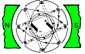
In real generators the armature coils are wound onto the armature using a variety of methods. Drum winding involves a number of coils separately wound round the armature and connected in series. In the figure below an armature is wound such that at every instant as it rotates two equal e.m.f's in parallel exist across the brushes.
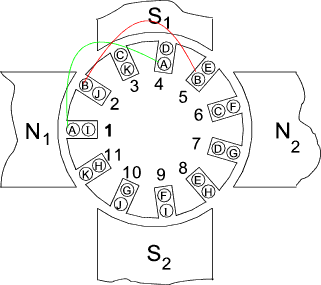
The figure below shows a 4-pole machine with and eleven slop armature core with eleven coils A-H. These coils may each have a number of turns.
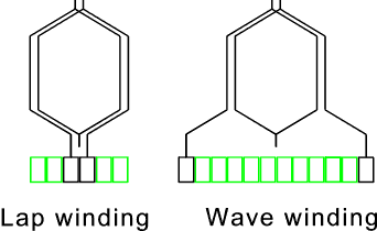
A number of methods are available for connecting the coils to the commuter segments. These can be broadly divided into two generic types as shown in the figure below. Lap windings and wave windings.
In lap winding the two ends of any coil are taken to adjacent segments of the commuter and in wave windings the ends are taken to spaced segments. A lap winding system has the same number of parallel paths as there are poles. The wave winding system has only 2 paths in parallel. e.m.f. generated in armature winding. Considering a generator with N poles (N = 2.p (pole pairs) , if Φ is the total flux from one pole and Nr is the armature speed (revs/s) then in each revolution of the armature each conductor cuts the total flux twice. flux cut per sec by each conductor = 2 Nr p Φ = e.m.f. in each conductor. If Z = the number of armature conductors and c is the number of parallel paths (2 for wave windings and 2 p for lap windings). E = 2 Nr p Φ. Z/c Note: the waveform of the generated e.m.f in each conductor follows that shown in the figure above under the commutation heading. E is the sum of a number of the individual average e.m.f. 's Field Windings The generator fields for very small dynamos is generally based on permanent magnets. For the
majority of industrial and utility generators the fields are produced using electomagnets.
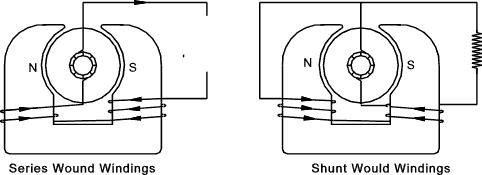
The electromagnets are often self energised (self-excited)and there are two methods of
wiring the fields to this purpose: series wound fields and shunt (parallel) wound fields.
For series wound fields the field coils consists of a few turns of heavy
gauge wire which carry the full supply current.
When current flows in the external circuit the e.m.f across the field is practically zero. A small current in the external circuit
results in a small magnetic field and hence a small e.m.f . Larger currents result in larger e.m.f.s but a maximum is attained when
the core is magnetically saturated. With higher currents the e.m.f of the generator drops as a consequence of the increasing p.d. across the
internal resistance of the windings. If the generator was short circuited the generator e.m.f. would fall to zero. V = E - IaRa In normal operation the armature resistance Ra is small and the terminal voltage remains reasonably constant. There is a tendency of the terminal voltage to fall off with increasing current. This can be offset by having a shunt wound generator with a few turns of series winding of thick wire. This arrangement, called a compound wound machine, produces a virtually constant supply voltage.... DC Electric Motors When a D.C generator armature is rotating the current flowing results in
an induced magnetic flux which tends to oppose the motion.
If this current is from an external source the induced flux would result in a
torque tending to cause motion.
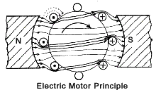
Each conductor on the armature of a motor contributes to the torque a force which is given by the formula F = B.I.l B = Flux in Webers, I =current in amperes, l = length of the conductor (m). The direction of the force is found by applying Flemings Left Hand Rule. (Flemings Left Hand Rule ) The principle of the action of the electric motor is shown below.
When the current flows in the armature conductors of a motor (or generator) a torque on the motor shaft results. (in a generator to torque is a reactive torque which must be overcome by the driver). This torque is T (Newton --metres). If the rotation speed of the shaft is N (revs/s) then the power (P -watts)developed by the motor = P = 2.π.N.T If the e.m.f across the armature conductors is E (generator e.m.f or motor back e.m.f) and the current in the armature windings = I a the electrical power in the armature = P = E.I a = 2.π.N.T However E is proportional to the rate of change of flux cut by the
armature conductors. This depends on the flux density over the pole faces.
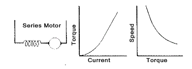
A series wound motor in arranged in a similar way to a series wound generator. The applied voltage V drives a current of Ia through the field and armature windings while a back e.m.f. of E is generated by the rotating armature. The formula for the applied voltage is V = Ia(Ra + Rf) + E On start up the series motor, the value of E is small and therefore Ia is large. Since the flux density of the field is roughly proportional to the field current. At this stage the following relationship applies
However as the field current is the same as the armature current
Therefore when a high starting torque is needed a series wound motor is suitable because Ia is large and therefore T is very large. E = V - Ia ( R a + R f ) and V is constant. Therefore E will increase which follows from
the motor speeding up. This increase compensates for the decrease in flux so that
the smaller the armature current the greater the motors speed until the armature, if unable
to provide enough centripetal forces, breaks up.
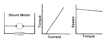
The shunt wound electric motor has the following relationship V = E + Ia.R a In a shunt wound motor the field is constant as it connected directly across the supply. The speed therefore does not rapidly increase on removing the load. On the other hand the starting torque is smaller than on the equivalent series wound machine since .
It has been shown above that T = E.I a / (2.π.N )
and therefore T.N = K. E.I a.........[K = 1/(2.π)] From this it is clear that a shunt wound motor tends to be a constant speed machine...
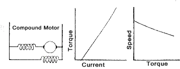
A series wound machine with an additional shunt winding, called a compound motor, has benefits of the series wound motor (high starting torque) with the benefit of the shunt motor (constant speed).
Cells, Batteries, Accumulators A cell is a device in which chemical energy is directly converted
to electrical energy. It comprises of two half cells connected in series
by the conductive electrolyte. A battery consists of one or more cells
in series. Each cell has a positive terminal, shown on diagrams by a long
line, and a negative terminal, shown by the shorter thicker line. These do
not touch each other but are immersed in a solid or liquid electrolyte.
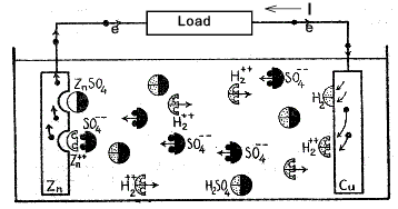
As current flows (electrons drift) through the external load the zinc
becomes less negative resulting in it attracting more sulphate ions.
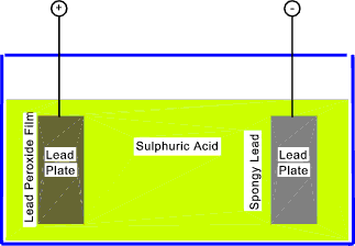
Secondary Cells A secondary cell is one which can be recharged many times by passing an electric current through it in the reverse direction to that for normal operation and reversing the chemical process. The most largely used high power secondary cell is the lead acid cell. A single lead-acid cell can develop an e.m.f under load of about 2V. A discharged lead-acid cell has a potential difference of about 1,75V dependng on the rate of discharge. The electro-chemical process involved in the lead acid cell is simply described below. If two lead plates are immersed in dilute sulphuric acid the surface of each becomes coated with a trace of lead sulphate. When current is passed through this cell, the lead sulphate on the anode is changed to lead peroxide and that on the cathode to metallic lead. In this condition the cell has an e.m.f. of about 2,1 volts. If the cell is discharged , both plates again become coated with lead sulphate. Continual charging and recharging increases the thickness of these chemical active layers, and as a result the capacity of the cell. This process of plate forming is expensive and is not used commerically. Normally the lead acid plates consist of lead-antimony alloy grids packed with a paste made from litharge (PbO), red lead (Pb3O4) and sulphuric acid. When the cell is first charged the whole thickness of the past changes: that on the anode becomes lead peroxide and that on the cathode becomes spongy lead. The grid is unaffected.
This type of cell has a large capacity and is
mechanically robust. Negative Plate (Cathode)....PbSO4 + H2++ --> H2SO4 + Pb Positive Plate(Anode)....PbSO4 + SO4- - + 2H2O --> 2H2SO4 + PbO2 During this process the sulphuric acid becomes more concentrated
(increased specific gravity from 1,12 to 1,26 is small accumulators and 1,17 to 1,21 in large units). The positive grid becomes filled with lead peroxide which is chocololate
brown in colour and the negative grid becomes filled with spongy lead (silver). Negative Plate (Cathode)....Pb + SO4- - --> PbSO4 Positive Plate(Anode)....PbO2 + H2++ + H2SO4 --> PbSO4 + 2H2O They plates become grey in colour, the e.m.f reduces and the specific gravity of the sulphuric acid falls. The above notes relate wet lead acid type. There are in practice a number of different types as listed in the table below Secondary Cell Types
Note :VRLA stands for valve regulated lead acid and is the designation for maintenance-free lead-acid batteries. VRLA batteries types include Absorbent glass mat battery , and Gel batteries. These batteries are often designated as sealed lead-acid batteries, but this term not exactly correct. A sealed battery would be a safety hazard due to overpressure risks when overcharging, and there is always a safety valve present, hence the name valve-regulated. Rectifiers A large part of the DC systems used in industrial and domestic systems
are rectified AC system. AC supplies are available everywhere and therefore
it is most convenient to use these existing supplies to power DC systems such as
battery chargers, portable radios etc.
Assuming the diodes have zero forward resistance and infinite back resistance then the instantaneous, values of the resulting rectified waveform are.
The rectified voltage and current mean and RMS values are shown below.
Full Wave Rectifier The full wave rectifier circuit shown is called a bridge rectifier network...
Assuming the diodes have zero forward resistance and infinite back resistance then the instantaneous, values of the resulting rectified waveform are.
The rectified voltage and current mean and RMS values are shown below.
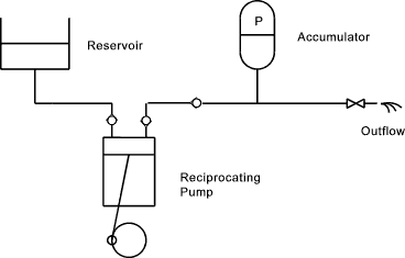
The rectifier circuits produce a voltage and current flow which is unidirectional but the variables still have a large variation in the form of a half sinusoidal pattern. Many systems require a continuous steady voltage/current to operate successfully. To achieve this a smoothing system is required. A very simple anology to an electical smoothing circuit is a hydraulic accumulator or reservoir system.
The above simple hydraulic system illustrates that that the reciprocating pump produces a fluctuating flow of approximately sinusoidal flow rate with no flow on its charging stroke. The accumulator pressurises when the pump is at full flow and discharges to the system when the pump outlet falls. This significantly smooths the flow such that the outflow is relatively continuous. A valve which adds resistance to the outflow helps with this smoothing process. The method of producing smoothing in a electrical circuit is to use capacitors as shown below.
Enhanced smoothing results from restricting the varying voltage component. This is achieved by including a cored inductance in series with the capacitor/load system as shown below. Having two capacitors with an inductance provides yet another stage of smoothing.
The above notes relate to the popular semi-conductor rectifier diode types but other types of rectifier are also using in industry including.
a) Using AC motors to drive DC generators More detailed notes on different types of rectifiers are found in the linked websites Resistance The electrical resistance is a measure of the degree to which an
material opposes the passage of an electric current. The SI unit of electrical
resistance is the ohm. Its reciprocal quantity is electrical
conductance measured in siemens. If a conducter had zero reisistance then
if an e.m.f. of any value where applied across its ends there would be an infinite current.
It is equivalent to friction in mechanical engineering.
A material which permits the free passage of current is called a conductor and one which opposes the passage of current called insulators. The energy lost as a result of resistance results in the generation of heat. This is very important in the rating of conductors and affects the selection of insulating materials. The resistance of a material is directly proportional to the length of the conducting path and in inversely proportional to its area.. A table of various resistivity values is included in Resistivity /Temperature Effects
Note: 1 Ω.m = 10 6Ω mm 2 /m |
Useful relevant Links
|
|
Electrics Index
Send Comments to Roy Beardmore
