Matter Index Page
Timber Index Page


Introduction..... Relevant Standards..... Symbols..... Design Methods..... Bending Moment and Shear Force Diagrams.....
Bending Stresses..... Shear Stresses..... Composite sections..... Beam Deflections.....
Structures..... Lateral Stability..... Bearing.... Test Methods.... Linked Reference Info


Structural Design Using Timber


Introduction

The notes below show in outline a number of principles used in calculating the strength of timber structural members.     The principles used are based on the requirements of BS 5268;    Part 2.     This codes is a permissible stress design code.    Other design methods are available including load factor design and limit state design .    These options will be addressed but they will not be treated in any detail on this webpage,


Relevant Standards

BS 5268-2 ;2002 Structural use of timber � Part 2: Code of practice for permissible stress design, materials and workmanship

BS EN 1912:2004: Structural timber Strength classes- Assignment of visual grades and species

BS 4978:1996 Specification of Softwood Grades for Structural Use.


Symbols
a = distance (m)
α = angle of grain (deg /rads)
A = Area (m2)
b = breadth of beam/thickness (m)
E = Modulus of Elasticity (N/m2
Emean = mean value Modulus of Elasticity (N/m2
Emin = min value Modulus of Elasticity (N/m2
G = Modulus of Rigity (N/m2 /Pa
h = depth of section (m)
i =radius of gyration (m)
I = Second Moment of Area (m4
L =Length /span/ (m)
Le =Effective Length /Effective span (m)
m = mass (kg)
n = number
λ = slenderness ratio
Q = First moment of area(m3
ρaverage = average density (kg / m3)
M = Moment (Nm)
σm.a,ll = Applied bending stress parallel to grain (N/m2)
σm.g,ll = Grade bending stress parallel to grain (N/m2)
σm.adm,ll = Permissible bending stress parallel to grain (N/m2)
Fv = Applied shear Force (N)
τm.a,ll = Applied shear stress parallel to grain (N/m2)
τm.g,ll = Grade shear stress parallel to grain (N/m2)
τm.adm,ll = Permissible shear stress parallel to grain (N/m2)
τr.a,ll = Applied rolling shear stress parallel to grain (N/m2)
τr.adm,ll = Permissible rolling shear stress parallel to grain (N/m2)
Δm = bending deflection (m)
Δs = shear deflection (m)
Δtotal = total deflection (shear + bending) (m)
Δadm = pemissible deflection (m)
σc.a,ll = Applied compressive stress parallel to grain (N/m2)
σc.g,ll = Grade compressive stress parallel to grain (N/m2)
σc.adm,ll = Permissible compressive stress parallel to grain (N/m2)
σc.a,l- = Applied compressive stress normal to grain (N/m2)
σc.g,l- = Grade compressive stress normal to grain (N/m2)
σc.adm,l- = Permissible compressive normal parallel to grain (N/m2)
σt.a,ll = Applied tensile stress parallel to grain (N/m2)
σt.g,ll = Grade tensile stress parallel to grain (N/m2)
σt.adm,ll = Permissible tensil stress parallel to grain (N/m2)


Design Methods

1) Permissible/Admissible design

Using this criteria the strength of a timber structure involves determining the stresses induced under working conditions and comparing them with the permissible/admissible stress.
The permissible stresses are obtained as the product of the grade stress for the timber and various modifying factors, some of which are listed below

  • K2 relates to the moisture content of the timber
  • K3 relates to the duration of the load.
  • K6 relates to the shape of the cross section.
  • K7 relates to the depth of the section
  • K8 relates load sharing factors.

Note :A detailed list of modifying factors is provided on webpage Modifying Factors.

Therefore

σm.adm,ll = σm.g,ll. K2.K3.K6.K7.K8

σm,ll         σm.adm,ll

σm,ll = Calculated bending stress parallel to grain
σm.adm,ll = Admissible bending stress parallel to grain
σm.g,ll = Grade bending stress parallel to grain

This method is used in BS 5268 and is used in the examples provided below

2) Load Factor Design


Using this criteria the strength of a timber structure involves determining the ultimate load stresses i.e the working stress x a factor of safety.    This is compared to the ultimate capacity of the timber sections at yield.    Plastic methods are required to determine the timber section capacities.

Working Loads x Factor of Safety Ultimate strength of timber at Failure

This method is not considered further in these notes.

3) Limit State Design


When using limit state design the load at structural collapse is divided by a selected margin of safety to determine the ultimate capacity of the structure..    The ultimate design load is determined as the product of the working load and a second selected safety margin.    The ultimate design load should be less /or equal to the ultimate capacity of the structure.

Ultimate design load         Ultimate capacity
Working (characteristic) load x partial factor of safety         Failure /collapse load x partial safety factor.

This method is used in most modern timber design codes including Eurocode 5.

This method is not considered further in these notes.


Beams..Bending Moment Diagrams and Shear Force Diagrams for beams

The nomenclature and sign convention for timber beams to BS 5268 is the same as that indicated on webpage Bending Moment - Shear Force Diagrams


Bending Stresses

The bending beam theory for timber beams is similar as that indicated on webpage Beam Theory


Shear Stresses

The stresses resulting from tranverse loading of timber beams is similar as that indicated on webpage Shear stress


Composite Sections

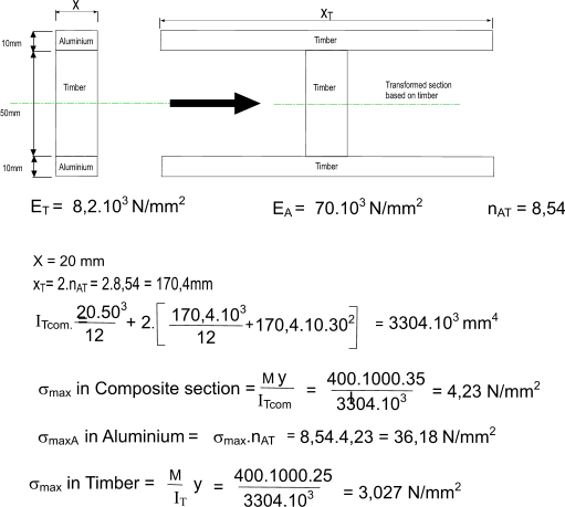
Timber beams used in construction are often fabricated from different materials e.g an I section beam can comprise softwood flanges with a ply-wood web.     The design of composite sections is illustrated on webpage Composite Sections

Example of a composite section calculation

Consider a composite section as shown below subject to a maximum bending moment of 400 Nm. What is the maximum stress in the timber section and the maximum stress in the Aluminium section


Beam deflections

For design of structures made of timber the limit of acceptable design is specified to avoid situations such as:

Misalignment of building items such as doors and windows
damages to finishes such as plasater or tiles
reduction of worry of people e.g crossing bridge or occupying building

According to BS 5268 part 2 the deflection of a beam /span is acceptable if the deflection when the member when fully loaded does not exceed 0.003 of the span.    For domestic floor joists, the deflection under full load should not exceed the lesser of 0.003 times the span or 14ζ mm, where;

ζ = 0.86 for floors whose transverse stiffness is provided by the decking/ceiling.

ζ = 1.00 for floors where there is additional transverse stiffness to that from the decking/ceiling. This additional transverse stiffness may be provided by herringbone strutting or by blocking of depth at least 75 % of the depth of the joists or, in the case of transverse members which are continuous across the joists (i.e. joists with an open-webbed structure), by timbers of depth at least 30 % of the depth of the joists.

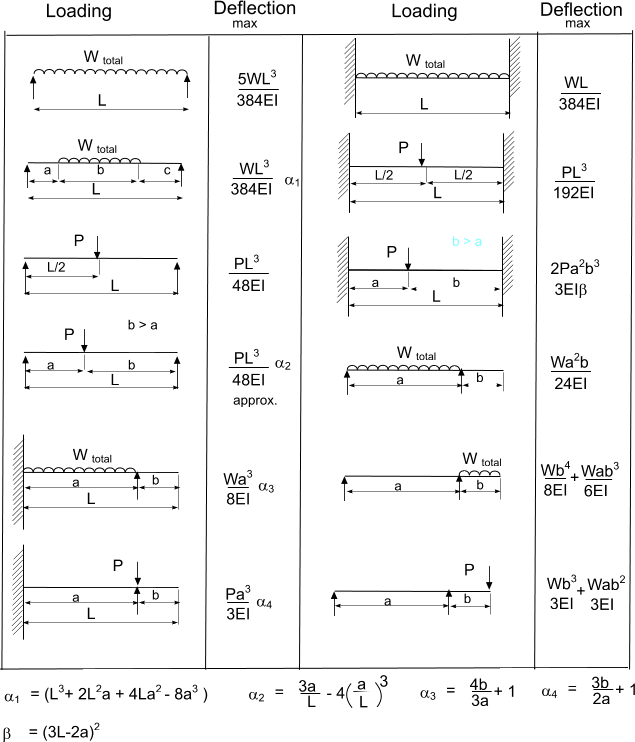
In a simply loaded beam the maximum deflection induced generally approximates to the mid-span value if it is niot actually equal to it.     The table below showing various standard load cases are is provided below


Timber structures

For structures made from timber beams operating within their elastic limits the design principles involved are similar to those used for steel structures. Structures


Lateral Stability of built in beams

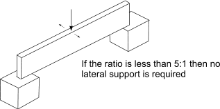
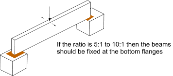
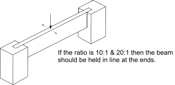
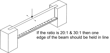
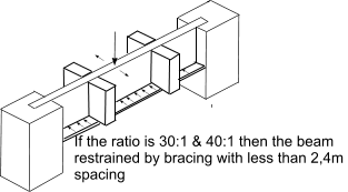
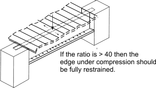
Beams with large depth to thickness ratios are at risk of buckling under bending forces.    BS 5268 uses the ratio of Ixx (2nd moment of area of section about neutral axis) to Iyy (2nd moment of area of the section perpendicular to the neutral axis ) to identify the support requirements such that there is no risk of bucking

Note: for a simple rectangular beam the Ixx/Iyy ratio is simply the square of the d/b ratio.

I xx/ I yy14916253649
d/b1234567


Bearing Strength

The timber properties when subject to concentrated compression loads e.g at support positions is somewhat complicated and is affected by both the length and the location of the bearing. The grade stress perpendicular to the grain is used to determine the permissible bearing stress.    For a bearing surface subject to a normal force of P the bearing stress σc.a

σc.a = P /Ab

Links Providing information on Wood
  1. Introduction to Structural Timber design to The Eurocodes..Very important document to latest codes :75 page document
  2. Canadian Wood Council ..Excellent site on Wood Engineering - my words
  3. Timber Trade Federation ..The Timber Trade Federation is the official voice of the UK timber trade.
  4. Timber Strength calculator..Canadian codes useful as a check
  5. Timber Size calculator ..Free on registration : In line with Eurocodes.
  6. Structural use of Hardwoods..Detailed information selection and Strength Grading

Matter Index Page
Timber Index Page