Control Index
Control System Response
|
Introduction
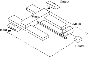
A typical system requiring control is a tool carrier moving along a slide by the action of
a DC motor which is controlled by a control which has an input set position signal and
slide position signal..The characteristic of the DC motor is that the developed torque is
proportional to the applied voltage. The motor drives the carrier using a direct
drive system such that the force is directly proportional to the motor torque.
The carrier has a mass (M)... The motor indirectly produces a force on the carrier (F)....
The force from the motor is proportional to the voltage from the control
F = k 1.V ..... The voltage from the control is proportional to
the difference in the set position signal x i and the carrier position x o... It is
assumed that control voltage V = k 2 ( x i - x o) = k 2 .x e...
F = k 1 .k 2.x e = k 1 .k 2 ( x o-x i ) The response of the motion of the system assuming negligible damping (Force = mass x acceleration) ... F = M d 2x /d 2 t In control engineering it is common to use the operator "D" in place of d/dt. ... Therefore k 1.k 2 ( x o - x i ) = M.D 2 x o M.dx o2 /dt 2 + k 1.k 2 x o = k 1.k 2 .x i Using Block Diagram notation this is shown as
System Response Definition The total response of a linear constant differential equation is the sum of the free response and the forced response.Another way of defining the total response is as follows..
System Response It is a primary function of control engineering to establish the response of the system to a particular input.. Considering a step input of x i = x a.. applied from time t = 0. It can be proved that the response of the system = x o = x a (1-cos ω n.t ) .... By making ω n2 = (k 1k 2 )/M
Note: In reality the actual mass would not oscillate but would tend to stop due to friction forces
within the system. The equation of motion for the system now becomes M.dx o2 /dt 2 + C. dx o/dt + k 1.k 2 x o = k 1.k 2 .x i The control block diagram is modified as follows..
Replacing k 1k 2 with K..... and using the D operator The equation of motion becomes M.D2x o + C. D.x o + K. x o = K .x i
Dividing throughout by M and Replacing ω n2 = K / M
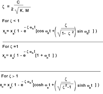
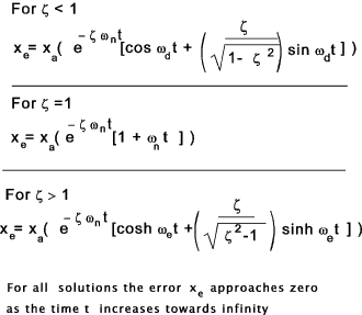
and using the damping factor ζ = (C/2) √(KM) (D2 + 2 ζ.ω n D + ω n2 ).x o = ω n2.x i For the step input x i = x a standard solutions are obtained.
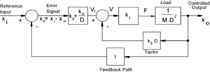
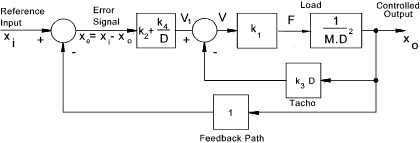
For this requirement damping provides an improvement. However viscous damping absorbs power and is accurate control using viscous damping is difficult. It is more practical to achieve the same effect by introduction of velocity feedback (C. D.x o ). This control scheme is shown below..
The equation of motion can be derived from the block diagram as follows. M.D2x o + C. D.x o + K. x o = K .x i
The damping C coefficient can be adjusted by simply adjusting the electrical signal from the velocity
feedback sensor. This method of providing damping is called output velocity feedback. A variation
of this principle is obtained by use of Proportional + Derivative control action ( P.D ) The system error equation includes the error terms on the LHS and the input variables on the RHS. The error equation relating to the above system is as follows. (M.D2 + C. D + K) x i - x e = K .x i..therefore If the input control requirement is a constant value i.e x a The derivatives of this with respect to time = 0. Therefore for a constant input value the error equation becomes.. (M.D2+ C.D + K ) . x e = 0 The error value is the input value the output value ( x i - x o ) . Therefore the solution to the above equation for a constant value x a is conveniently obtained from the above solutions as follows:
The error resulting from inputs which are time related i.e ramp or sinusoidal are
much more complicated. (M.D2 + C.D ). r a t = C. r a The error equation becomes (M.D2+ C.D + K ) . x e = C. r a The is very similar to the equation of motion for the system with damping
with x o replaced by x e and K .x i replaced by C. r a
The transient component are obtained as above. K . x e = C. r a Therefore x e = (C /K ). r a
Having a residual error is normally not satisfactory. A method of eliminating this error is to include an Integral control action...This may be done by adding an integral function to the error signal conditioning unit as follows
In the D notation this is shown as follows
The block diagram is modified accordingly as follows:
The equation of motion can be derived from the block diagram as follows. (M.D2 + C.D + K + I/D ) x o = (K + I/D ) x i Replacing x o with x i -x e results in the equation for error vs input x e vs x i (M.D2 + C.D + K + I/D ) (x i - x e) = (K + I/D ) x i therefore Again consider the case x i = r a.t. The RHS of the error equation becomes.. (M.D2 + C.D ). r a t = C. r a The error equation becomes (M.D2+ C.D + K + I /D ) . x e = C. r a To convert this to a pure differential equation it is simply differentiated through with respect to time which effectively involves multiplying x D. The RHS (C.r a ) is a constant which when differentiated with respect to time = 0.. (M.D3+ C.D2 + K.D + I ) . x e = D.C. r a = 0 The introduction of the Integral function has eliminated the constant steady state error but has raising the order of the control equation from a two to three and the result of this has been to increase the risk of stability problems...Stability is covered separately... Control Analysis The above outline notes introduce the general control principles in the time domain. Much of the analysis of control systems are completed by taking laplace transforms and analysing the resulting equations using root loci, Nyquist of Bode plots.. These areas of work are covered in outline on the following pages. |
Sites & Links For Control Information
|
|
..Page is being constructed..
Control Index
