Shaft
A shaft is a rotating or stationary component which is normally circular in section.
A shaft is normally designed to transfer torque from a driving device to a driven device.
If the shaft is rotating, it is generally transferring power and if the shaft is operating without rotary
motion it is simply transmitting torque and is probably resisting the transfer of
power. A shaft which is not rotating and not transferring a torque is an axle.
Mechanical components directly mounted on shafts include gears, couplings, pulleys,
cams, sprockets,links and flywheels. A shaft is normally supported on
bearings. The torque is normally transmitted to the mounted components
using pins, splines, keys, clamping bushes, press fits, bonded joints and sometimes
welded connections are used. These components can transfer torque to/from the shaft
and they also affect the strength of the shaft an must thereore be considered
in the design of the shaft.
Shafts are subject to combined loading including torque ( shear loading ),
bending ( tensile & compressive loading ), direct shear loading, tensile loading and
compressive loading. The design of a shaft must include consideration of the
combined effect of all these forms of loading. The design of shafts must
include an assessment of increased torque when starting up, inertial
loads, fatigue loading and unstable loading when the shaft is rotating at
critical speeds (whirling).
Notes:
For information on the bending and shear stresses resulting from side and axial loads refer to
Beam Index
For information on the critical speed of shafts refer to webpage Shaft Critical Speeds
For information on the fatigue considerations refer to webpage Fatigue index
For information on the design requirements of keys & splines Keys/splines index
When designing a shaft the following staged procedure is normally adopted
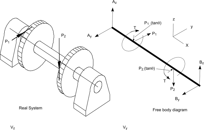
- Produce a free-body sketch of the shaft. Replacing the various associated components with their equivalent load/torque
components
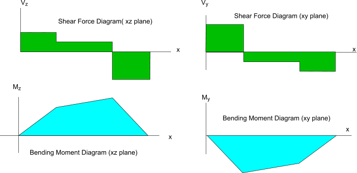
- Produce a bending moment diagram for the xy plane and the xz plane (x = shaft axis direction).
Note: The resulting internal
moment at any point along the shaft = Mx = Sqrt (Mxy2 + Mxz2 )
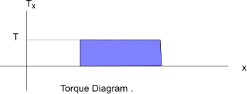
- Produce a torque diagram.
- Locate the section(s) on the shaft where the combined internal loading is the highest..This important stage requires significant effort and judgement
- Assess the strength of the shaft and determine if the safety margin is sufficient.
The failure criteria (ref Failure theories for the shaft depends on the material selection (ductile/brittle) and consideration of the loading
regime, (constant/ variable loading, rotating speed, degree of shock loading )
- Check that the radial and angular deflections of the loaded shaft are acceptably low.
|
Sketches illustrating stages 1,2, & 3
Stage 1 -- Produce a free-body diagram
Stage 2 -- Produce a bending Moment diagram
Stage 3 -- Produce a Torque diagram
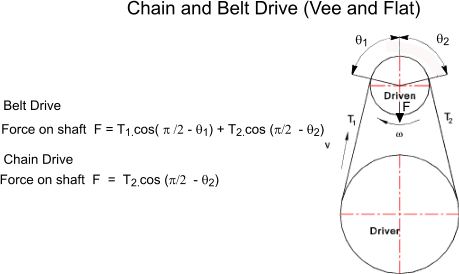
Forces
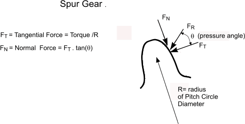
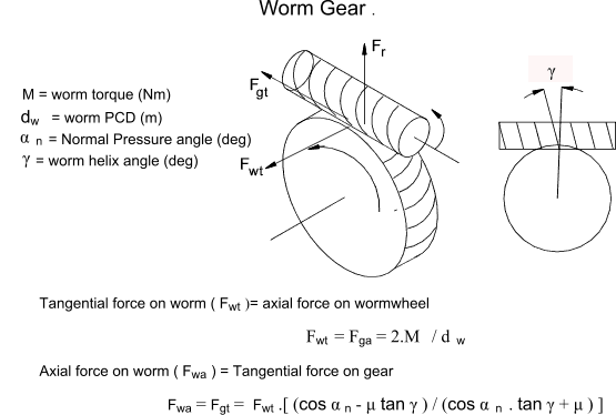
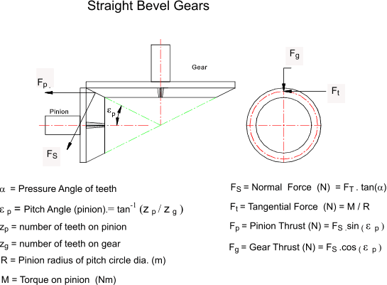
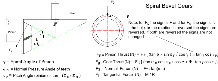
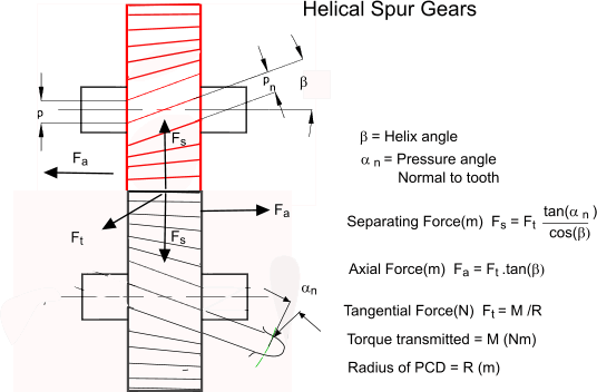
The resulting forces on a shaft resulting from different drive components are listed below
Basic Equations
The various equations required to evaluate the stresses and strains in a loaded shaft and to arrive
at safe operating loads are to be found on other webpages. The simple equations below related to the estimating
the torque resulting from a transmitted power and the surface shear stresses resulting from a transmitted torque.
- S y = Tensile yield strength (N/m2)
- S sy = Shear yield strength (N/m2)
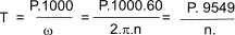
- T = Shaft Torque (Nm)
- P = Power transmitted (kW)
- n = RPM ( revs/min )
- D = Shaft diameter(m)
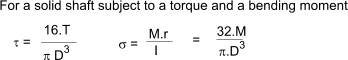
- T = Applied torque (N.m)
- M = Applied bending moment (N.m)
- KM = Shock fatigue factor. ( Moments )
|
- Kt = Shock / fatigue factor. (Torques.)
- σ = Direct stress (N/m2)
- σx ,y, z = Direct stress z ,y and z directions(N/m2)
- σ1 ,2, 3 = Principal Stresses(N/m2)
- τ = Shear stress (N/m2)
- τ xy = Shear stress in xy plane (N/m2)
- ω = angular velocity (rads/s)
- θ = angular deflection (rads)
|
Assuming the shaft is made from a ductile material the failure
criteria applicable is the Maximum Shear Stress Theory (MSST)
criteria. ref. Failure Criteria
This is very relevant to ductile metals. It is conservative and relatively easy to
apply. It assumes that failure occurs when a maximum shear stress attains a
certain value. This value being the value of shear strength at failure in
the tensile test. In this instance it is appropriate to choose the yield point
as practical failure. If the yield point = Sy and this is obtained from a tensile
test and thus is the sole principal stress then the maximum shear stress Ssy
is easily identified as Sy /2 .
Ssy = Sy /2
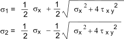
Maximum Shear Stress = τ max = Greatest of
( σ1 - σ2 ) / 2 :
( σ2 - σ3 ) / 2 :
( σ1 - σ3 ) / 2 =
( σ1 - σ3 ) / 2
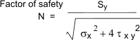
The factor of safety selected would be
FoS = Sy / ( 2 . τ max )
= Sy / ( σ1 - σ3 )
For the simple case of a tensile stress σx combined with a shear
stress τ xy . with the principal
stress σ3 = 0. and σy ,σz
τ xz , τ zy = 0. .. (ref to notes on Mohrs circle)
.. Mohr's Circle The two non-zero principal stresses are
The resulting FoS =
Or in terms of Torque and bending moments.
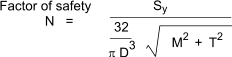
Important note:
The above equations are very basic equations taking no account of fatigue conditions, stress concentration factors,
etc.. It is also necessary to consider the linear/angular deflection of the shaft to ensure it is within
acceptable limits. A variation of the above equation ( based on equation in Machinerys Handbook ) taking into account combined fatigue and shock loading is
provided below.
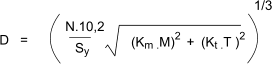 |
Type of Load | Km | Kt |
| Gradually applied load and steady | 1,5 | 1,0 |
| Suddenly applied/ minor shocks | 1,5-2,0 | 1,0 - 1,5 |
| Suddenly applied heavy shocks | 2,0 -3,0 | 1,5 - 3,0 |
Shaft Deflection
It is important that a shaft should not only have the strength to transmit the
specified torque and load without the risk of failure but also that shaft deflections due to bending and torque
are within acceptable limits. The limiting of the angular /radial deflection is required by the need
to reduce vibration and ensure reliable operation of the related components including
gears, splines bearings etc. The design procedure for a shaft should therefore include an
appraisal of the resulting deflections when the shaft is loaded. If it is deemed necessary to calculate the
angular and linear deflections due to bending at critical points then various methods are available.. some of these methods
are identified on webpage Shaft Deflections. Notes on torsional deflections
are provided below
Angular Deflection_Due to bending
| Type of bearing | Max angular deflection [�] |
| Single-row ball bearings | 0,23 |
| Double-row self-aligning ball bearings | 2,0 |
| Cylinderical roller bearings | 0,06 |
| Taper roller bearings | 0,03 |
| Spherical ball bearings | 0,5 |
| Spherical roller bearings | 12,5 |
| Single-row tapered roller bearings | 0,03 |
| Thrust spherical roller bearings | 2,0 |
| Sliding bearings (b/d < 1) | 0,05 |
Radial deflection due to bending.
The maximum radial deflection at the teeth for spur gearing = 0.01 * m and for bevel and worm wheels = 0.005 * m
(m = module of gear wheel (mm)). The suggested maximum deflection (not at gears) for general engineering = 0.0003 * L
and for machine tools = = 0.0002 * L .(L...distance between bearings).
Torsional Angular Deflection
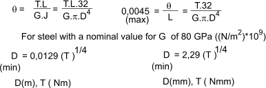
The angular deflection of a shaft is obtained by the equation
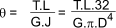
In Machinerys handbook 27th ed a safe maximum deflection of 0,26 degrees per m length (0,0045 rads/m) is recommended. Therefore
Indicative Transmittable Torque Values
This table is provided to allow comparison between shafts and is based on very simplistic assumptions with no allowance for fatigue, additional stresses to Bending Moments etc etc etc
| Shaft Dia |
Pure Torque |
Power (100RPM) |
Power (1500RPM) |
| mm |
Nm |
kW |
kW |
| 30 |
132 |
1,4 |
20,8 |
| 40 |
314 |
3,3 |
49,3 |
| 50 |
614 |
6,4 |
96,4 |
| 60 |
1060 |
11,1 |
166,5 |
| 75 |
2071 |
21,7 |
325,3 |
| 80 |
2513 |
26,3 |
394,8 |
| 100 |
4909 |
51,4 |
771,1 |
Notes on table values
τ = The skin torsion stress of a solid round shaft :
T= The torque transmitted by the shaft : T = τ.π.D3/16
The table is based on a torsion stress level of 25 N/mm2
Power transmitted by a shaft P = 2 * π * T * N (N = Revs /sec)
Table power based on pure torque values
Methods of Locking/Driving items on Shafts
| Type |
Description |
Notes |
| KeyWay |
Reliable method based on a machined keyway in shaft and associated bore. Drive is via a fitted key. Results in increased local intensified stresses. A machined keyway results in a weaker shaft.(shaft dia. effectively reduced by 25%). Key can be deformed over time and result is a loose drive |
Keyways
Splines |
| Pin |
Very low cost option. Used for low torque drives. |
Circlips
Pins |
| Spline |
Expensive to manufacture with matching spline in shaft and bore. No additional components required. Allow relative axial movement. High torque capacity. |
Keyways
Splines |
| TaperLock Bush |
A tapered bush that fits into a tapered bore in the Gear/Coupling to be driven by the shaft. The locking action results from forcing the bush into the bore using axial screws. Tendency to stick in position. Limited shaft range (up to 80mm dia) |
|
| Shaft Locking Lock Bush |
Similar principles to taperlock bush but has parallel bore and OD. More convenient to install. Much larger size range (up to 500mm dia). These are relatively expensive but required no special shaft machining. |
|
| Interference Fit |
Requires accurate shaft and bore. Machined items are assembled using hydraulic press or
using thermal methods e.g. Heating the female item or freezing the male item. Difficult to separate. This method if correctly engineered is
probably a near ideal method with minimum fatigue risks |
Interference fit |
| Polygon Drive |
Shaft ground to a profile rounded triangle or rounded square. The polygon profile has excellent fatigue properties,
constant inertia and has around 30% more load carrying capability when compared to splines/keyways etc of the same size.
|
|
| Adhesive |
Low Cost. High torques can be transmitted. No special machining of shaft or bore. Cannot easily be taken apart. Should not be used without extensive development/testing |
Adhesives |
| Hydraulic Locking Bush |
Similar application to locking bush. Large size range. Convenient to apply. No risk of sticking. Relatively expensive. |
|
|